More About Positioning a Foreshortened Extremity Manually | ||||
|
| |||
For radius dimensions, you can select the Foreshortened check box through Edit > Properties > Dimension Line tab.
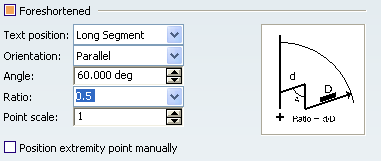
Selecting this check box allows you to transform a radius dimension line into a foreshortened radius dimension line by defining the following parameters:
- Text position: Select the text position as Long Segment or Short Segment.
- Orientation: Select the dimension text orientation as Parallel or Convergent according to the dimension line.
- Angle: Type the value or use the arrows to change the value.
- Ratio: Select the required ratio (short segment/long segment) value from the list.
- Point scale: Type the value or use the arrows to change the value.
- Position extremity point manually: Select this check box if you want to position the extremity point of the foreshortened dimension line manually (in this case, you can move the extremity point using a yellow manipulator).
You can position the foreshorten extremity in any one of the following ways:
- Freely anywhere without any association: This is non-associative mode and free from restrictions.
- On a linear element that represents the center of the circle: This association is persistent and may be updated each time the referenced element is modified. This is associative mode and only possible under the following possible conditions:
| Element Type | Condition |
|---|---|
| An axis line | Circle center is coincident with the axis. |
| An axis of a center line or a thread | Circle center is coincident with this axis. |
| A 2D line interactively sketched (that is not generated from 3D) | Circle center is coincident with the line. |
| Any 3D curve whose projection onto view plane consists in a line | Circle center is coincident with the projection of this line onto the view plane. |
| Any surface whose projection onto view plane consists in a line | Circle center is coincident with the projection of this plane onto the view plane (plane is at least normal to view plane). |
Note: During dimension update, if the reference element is not retrieved or in case the reference element is not coincident with the center anymore, the update does not modify dimension display. In this case, the dimension becomes not up-to-date and you can identify it due its specific color (Dimensions for which last update failed color is applied).