More About Creating Dimensions between Intersection Points | ||||
|
| |||
Understanding Dimensions between Intersection Points
This sub-topic provides background information to help you understand dimensions between intersection points.
There are two types of intersection points: definite intersection points or fictive intersection points.
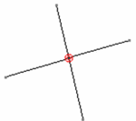
A definite intersection point is the meeting point of 2 curves which physically intersect each other.

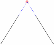
A fictive intersection point is the meeting point of 2 fictive curve extensions, or a curve and a fictive curve extension.

Creating a dimension between intersection points is a sort of "shortcut" that combines the creation of 2D intersection points, construction lines, coincidence constraints (on 2D elements only), a 2D line and a dimension all at once. There is no actual link between the dimension and the geometry on which it is based.
The table below summarizes the kind of intersection detected in Drafting and 2D Layout for 3D Design, depending on the type of element pointed by the mouse.
| The following kind of intersection... | is detected between... |
|---|---|
definite intersection |
straight 2D lines |
fictive intersection |
a straight 2D line and the extension of a straight line |
fictive intersection |
2 extensions of straight lines |
The table below summarizes the kind of intersection detected in 2D Layout for 3D Design only, depending on the type of element pointed by the mouse.
| The following kinds of intersection... | are detected between... |
|---|---|
definite intersection fictive intersection |
3D curves (edges or wireframe) which are projected as lines in the background of layout views |
definite intersection fictive intersection |
a straight 2D line and a 3D curve projected as a line in the background of layout views |
![]()
Dimensioning Commands Supporting Intersection Point Detection
This sub-topic lists the dimensioning commands which support intersection point detection.
The detection of intersection point when dimensioning is supported by the following commands:
- Dimensions
- Chained/Cumulated/Stacked Dimensions
- Length/Distance Dimensions
- Radius Dimensions
- Diameter Dimensions
![]()
Definition of Intersection Points in the Standards
This sub-topic provides information about the definition of intersection points in the standards.
The display and behavior of intersection points is defined by the administrator in the standards. Indeed, the administrator can specify the style that should be applied to the intersection point and construction line, whether the intersection point can be printed or not, and whether construction lines should be displayed and/or printable. For more information, refer to Dimension Parameters.