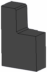
Creating Chamfers

Chamfering is an operation of removing or adding a flat section from a selected edge to create a beveled surface between the two original faces common to that edge. You can create two chamfers by selecting two edges.


Before you begin: To perform this task, create a sketch then extrude this sketch.
Related Topics
More about Chamfers
  1. Click Chamfer in the Operations toolbar.

    The Chamfer Definition dialog box appears.
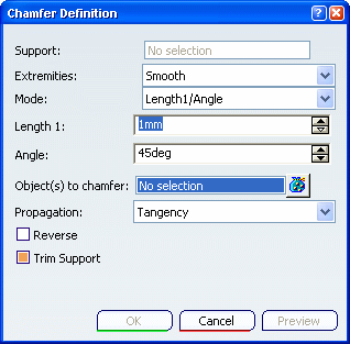
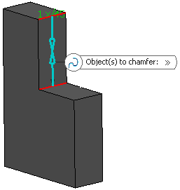
  2. In the Object(s) to chamfer box, select the edges to be chamfered.


    Important:
    • Chamfers can be created by selecting a face: the application chamfers its edges.
    • The Support box automatically displays the feature to be chamfered once the first edge belonging to this feature is selected. It is always grayed out. Edges to be added must belong to the same feature. Otherwise you need to remove the edges first.

  3. In the Mode list, select the desired mode:


    • Length1/Angle (default mode, i.e. intersection of the two perpendiculars of the normal lines): enter a length value and an angle value
    • Length1/Length2: enter two length values
      Important: The Symmetric extent check box appears: select it to define the same value for both lengths (Length 2 is no longer available)
    • Chordal Length/Angle: enter a chordal length value (i.e. the chamfer width) and an angle value

      Note:

      Width = Length / cos(Angle)

    • Height/Angle: enter a height value (i.e. distance between the intersection of the two adjacent faces and the chamfer face) and an angle value

      Note:

      Height = Length * sin (Angle)

  4. Here, enter a length value and an angle value, for instance 5mm and 45deg.

  5. Optional: Click Preview to see the chamfers to be created.
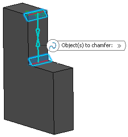


    In our scenario, because both selected edges imply no tangencies, the choice of a propagation mode is unnecessary.

  6. Select the Reverse check box to reverse the direction of the chamfer.

    You can also click the blue arrow in the geometry.

  7. Select the Trim Support check box to trim the support and assemble it to the chamfer.

  8. Click OK to create the chamfers.

    The element (identified as Chamfer.xxx) is added to the specification tree.