Displaying and Modifying the Dimensions of a Feature Directly

You can quickly display and modify a feature's dimensions in the 3D area, i.e. its length parameters (length, diameter and radius), angle parameters and fillet parameters.

It provides manipulators when passing over a dimension in order to dynamically modify its value. Moreover, it displays a length or angle ruler during the value modification in order to give a better display of the value and an easier way to control the modification thanks to the ruler's graduations.

This task shows you how to:


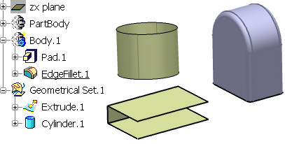
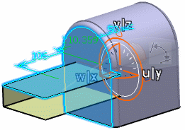
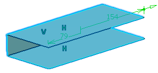
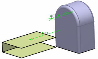
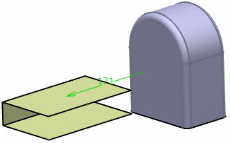
Before you begin: This capability is available on surfaces, solids and volumes. Create a 3D shape containing, for instance, a surface and a solid. In our scenario, we will be working with an extruded surface, a cylinder and a filleted pad:


Related Topics
More about the Edition of Parameters

Use the Robot

You can use a robot to quickly display and modify a feature's dimensions in the 3D area.

This is the quickest and easiest way to use this capability.

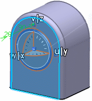
  1. Drag the robot from the upper right corner onto the pad.

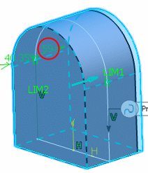
    The feature is selected and its associated parameters are automatically displayed and can be manipulated:

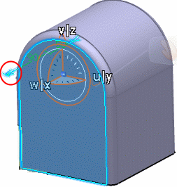
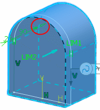
  2. Drag an arrow to modify the dimensions of the pad and release when satisfied (red-circled arrow in the image below).


    Note: You can sequentially display the parameters of several features by selecting another feature once you are done with the first one. In this case the parameters of the first feature are removed and those of the second feature are displayed.

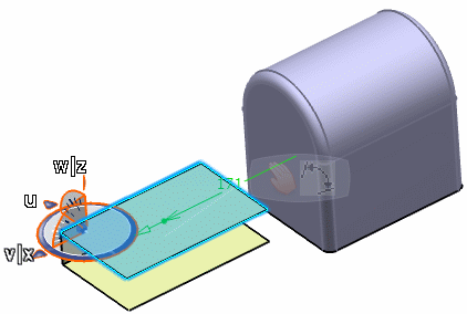
  3. Move the robot from the pad to the extruded surface.

    The parameters of the pad are no longer displayed and the parameters of the extruded surfaces appear.

  4. Drag an arrow to modify the dimensions of the extruded surface and release when satisfied.


  5. Press Esc or put the robot back to the upper right corner to exit the command.

    Tip: You can also take benefit of the multi-selection capability: simply click the Ctrl key and select several features. The parameters of the selected features are displayed simultaneously:

Warning: There is no automatic update even if you are working using the automatic update mode.

Use Parameters When Creating or Editing a Feature

You can modify all the parameters that appear in green in the 3D area when creating or editing a feature (as in our scenario).

  1. Double-click on the pad in the specification tree to display the Pad Definition dialog box.

    The manipulation arrows also appear if the pointer is located where the arrows have to appear.

  2. Move the pointer over a manipulable parameter.

    One or more arrows appear next to the parameter value to indicate the direction of the manipulation.

    Tip: You can also manipulate the length (an arrow appears at the end of each length):

    Note: The direction is always displayed in order to increase the parameter value when manipulating it. If you drag the arrow the opposite way, the value will decrease.

  3. Click and drag the arrow on the extremity of the dimension line and release when satisfied.

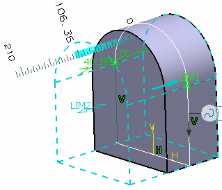
    A ruler appears as the length parameter is being modified.

    Important: It gives you a visual feedback but it is not possible to interact with it.


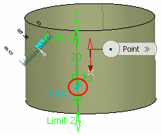
    Tip: A ruler also appears in case of an angle parameter to be modified. Here is an example with the cylinder:

  4. Click OK to save the changes.

Edit Parameters Using the Contextual Menu

You can modify all the parameters that appear in green in the 3D area when editing a feature using the Edit Parameters contextual item.

  1. Right-click the extruded surface in the specification tree.

  2. Select Extrude.x object > Edit Parameters from the contextual menu.

  3. Drag an arrow to modify the feature's dimensions.


  4. Press Esc to exit the modifications.

Edit parameters Using the Tools Menu Bar

You can activate a setting to permanently display the parameters after having selected the Extrude.x > Edit Parameters contextual item.

  1. Select Tools > Options > Infrastructure > 3D Shape Infrastructure.

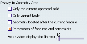
  2. From the Display tab, select the Parameters of features and constraints option.


    Note: It is cleared by default.

    Parameters are displayed in the 3D area and will always be displayed unless the option is cleared.

  3. Select the Edit Parameters contextual item on the pad.

    The Edit Parameters dialog box is displayed.

    Note: The Permanent display of parameters with value option is selected by default.

  4. Clear the Permanent display of parameters with value option and click OK.

    The parameters of the pad are no longer displayed in the 3D area.

Important: If you perform step 3 again, the Edit Parameters dialog box will still be displayed but the Permanent display of parameters with value option will be cleared. If you do not want this dialog box to appear anymore, you need to clear the Parameters of features and constraints option in theTools menu bar.
Warning: There is no automatic update even if you are working using the automatic update mode.

Display the Parameter Definition Dialog Box

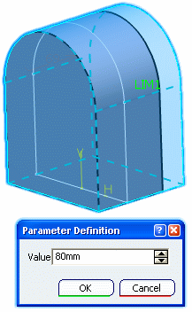
The Parameter Definition dialog box is available when a value is displayed in the 3D area, whatever it has been displayed using the robot, through the Edit Parameters contextual item or by editing the feature.

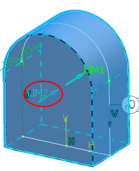
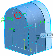
  1. Double-click any value in the 3D area (in our scenario, the red-circled value).


    The Parameter Definition dialog box appears.

  2. Use the spinners to modify the value.

    The display automatically updates and the object is modified accordingly.

  3. Click OK to apply the new parameter value.