Modifying Geometrical Tolerances
This task shows you how to modify a geometrical tolerance.
Double-click the geometrical tolerance you want to modify.
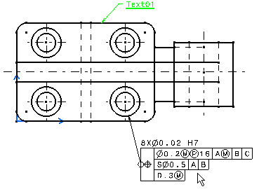
The Geometrical Tolerance dialog box is displayed, with
the existing values pre-entered.
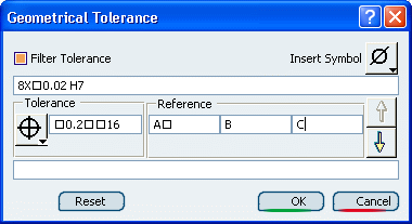
Modify the values as desired, as explained in
Creating a Geometrical Tolerance.
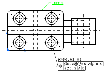
Click OK.
Click in the free space to validate the geometrical dimension modification.
Create a dimension,
then Creating a Geometrical Tolerance on it.
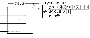
Click the extension line and move the dimension.
You can see that the geometrical tolerance follows the dimension.
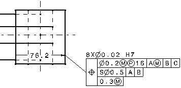
Click the geometrical tolerance and move it.
You can see that it has not impact on the position of the dimension.
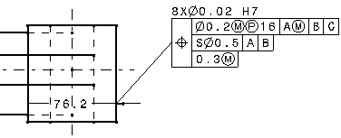

Associativity Between
the Dimension and the Geometrical Tolerance
You can create associativity between the dimension and the geometrical tolerance.
Create a dimension.
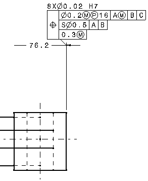
Creating a Geometrical Tolerance on it, selecting the dimension line.
Move the dimension.
You will note that the positioning and the length of the tolerance leader
remain constant when moving the dimension, whatever the dimension type.
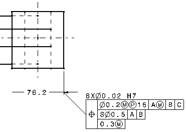
Create a dimension .
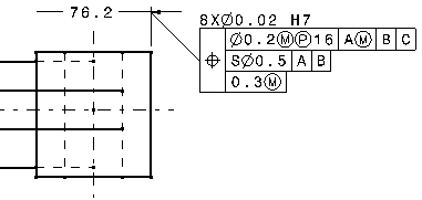
Creating a Geometrical Tolerance on it, selecting the extension line.
Move the dimension.
You will note the length of the tolerance leader is recomputed as long
as the dimension is moved.
This is due to the fact that the ratio between the lengths of the leader's
projection and the extension line's projection remain constant.
The positioning of the leader is also recomputed so that the distance
between the anchor point of the tolerance and the extension line remain
constant.
|