Creating Chamfer Dimensions | |||||
|
| ||||
Create Chamfer Dimensions Manually
You can create chamfer dimensions manually.
Click Chamfer Dimensions
 in the Annotations toolbar (Dimensions sub-toolbar).
In the Tools Palette which is displayed, you can choose:
- The format of the dimension:
-
Length x Length
-
Length x Angle
-
Angle x Length
-
Length
-
- The representation mode:
-
One symbol

-
Two symbols

-
Important: You can also access these options using the contextual menu: at any time during the chamfer dimension creation, you can right-click to display the contextual menu. - The format of the dimension:
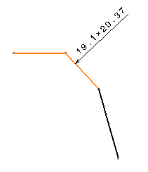
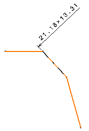
Choose the Length x Length format and the One symbol mode
.You have two options:
- Click the sheet to end the dimension creation. The chamfer
dimension is computed with an implicit second reference
line that is perpendicular to the first one.
- Select a second reference line or surface. In this case,
the chamfer dimension is computed according to both reference
lines you selected.
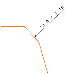
Important: In a Generative Drafting context (i.e. in the case of a generative view), you must apply the second option, i.e. you must explicitly select the second reference line. In any case, the dimension is associated to all the elements you selected.
- Click the sheet to end the dimension creation. The chamfer
dimension is computed with an implicit second reference
line that is perpendicular to the first one.
![]()
Create Chamfer Dimensions Using Chamfer Detection
You can create chamfer dimensions using chamfer detection.
Note that chamfer detection is provided as a help in selecting chamfers. However, depending on the geometrical configuration, it may not detect all chamfer types. If your chamfer is not detected, you can still create the chamfer dimension manually as explained below.
Open a drawing representation containing at least one chamfer.
Click Chamfer Dimensions
in the Annotations toolbar (Dimensions sub-toolbar).In the Tools Palette which is displayed (as well as in the contextual menu), you can choose the format of the dimension and the representation mode. For more information, refer to step 3 in Creating chamfer dimensions manually.
Choose the Length x Length format and the One symbol mode
.Fly the mouse over the element to be dimensioned. You can notice that, depending on where you position the cursor, the auto-detection agent indicates a different order for taking elements into account when creating the chamfer dimension:
-
1 indicates the element to be dimensioned.
-
2 indicates the line which will be used as the first reference.
-
3 indicates the line which will be used as the second reference.
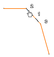
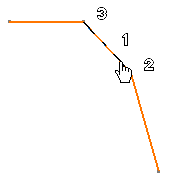
-
Click to end the chamfer dimension creation.
The dimension is associated to all auto-detected elements.