Handling Annotation Leaders | |||||||
|
| ||||||
Right-click the yellow control point at the end of the leader.
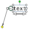
The leader's contextual menu appears.
Choose from the available options.
Note: Multi-selection is not taken into account for these options, except for Symbol Shape. The operation is performed only on the leader you right-click in the selection.
-
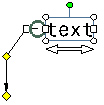
To add a breakpoint on the leader, select Add a Breakpoint.
-
To remove a breakpoint, right-click the breakpoint and select Remove a Breakpoint.
-
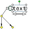
To add an extremity to an existing breakpoint (for texts or welding symbols only), right-click the breakpoint, select Add an extremity, and then click where you want to position the extremity.
-
To remove an extremity, right-click the additional extremity and select Remove Leader/Extremity.
Note: Clicking on the main leader extremity will remove the leader.
-
To add an interruption, select Add an Interruption and then, on the leader, click the two points between which you want to add the interruption.
-
To remove an interruption, right-click the leader yellow control point and select Remove Interruptions.
Important: Any existing interruption will be removed from the leader when adding or removing breakpoints. -
To remove the leader, select Remove Leader/Extremity.

-
To add an application zone symbol, point to Application Zone . Then select No Zone if you do not want a symbol, or select the required symbol from the following available symbols:
- Global All Around
- Partial All Around
- Global All About with horizontal axis indicator
- Global All About with vertical axis indicator
- Partial All About with horizontal axis indicator
- Partial All About with vertical axis indicator
- Global All Over
- Partial All Over

These symbols are used to specify that a specification is to be applied all around, all about or all over the 3D profile of a part. You can also specify whether it is to be applied globally or partially. This complies with ISO, JIS and ASME international standards.
Notes:
- When you update the pre-V6R210 standard, the display of all around and all over symbols changes according to new standard specification.
- The anchor symbol is not available on additional extremities.
-
To modify the leader symbol shape, point to Symbol Shape. Then, select No Symbol if you do not want a symbol for the leader, or select the symbol you want from the available symbols.
Important: Changing the symbol shape behavior differs depending on whether one or several annotations in the selection have more than one leader: - If the leader you right-click is the only one in the annotation, then the symbol is applied to this leader and to all annotations which have only one leader.
- If the leader you right-click is not the only one in the annotation, then the symbol is applied to this leader only.
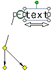
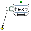
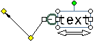
Move the leader or any existing breakpoints by clicking a yellow control point and moving it using the pointer.
-
To move the annotation but not the leader, click the annotation and move it using the pointer.
-
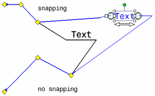
To move the leader along with the annotation while making sure the leader keeps its original shape, select Rigid and then move the annotation.
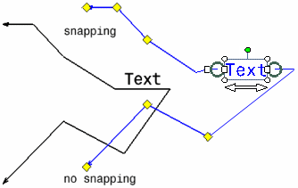
Important: - This functionality is available for texts, welding symbols, 2D components, tables and geometrical tolerances, but not for other annotation types.
- This functionality also applies when rotating the annotation text using the rotation manipulator.
-