Click Unfolded View
 in the Views toolbar (Projections sub-toolbar).
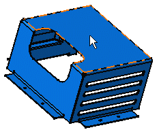
Select a surface on the part.
This will automatically use
the sheet metal reference wall plane.

Note:
If you prefer to specify which plane should be used, you can select
the plane in the Sheet Metal specification tree.
Click the sheet.
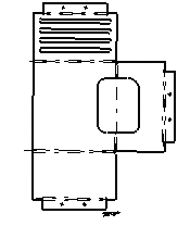
The unfolded view is displayed. It shows the axis lines resulting
from bend axes, as well as bend limits. These axis lines and bend limits
are represented as dashed lines.
With sheet metal parts containing holes, the hole axes (center
line) are also represented on the view.

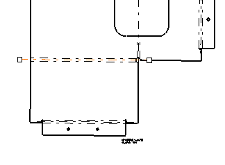
Optionally, if you want to modify an axis line, you can select
it.
Manipulators appear, allowing you to modify this line.


