Click Start
 in the Bar, then select Mechanical > Drafting.
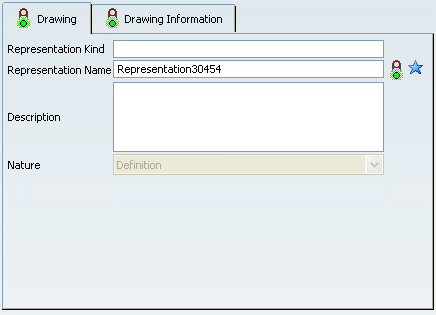
The Drawing / Representation DS dialog box appears.

In the Drawing tab, optionally specify the representation
kind, enter a name for your representation, and a description. By default,
a name RepresentationX (where X is a number) is specified.
For more about the Drawing tab and general representation attributes,
refer to Infrastructure
User's Guide: Creating an Object.
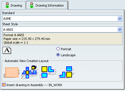
Click the Drawing Information tab.
This tab lets
you define various information related to your drawing.

Select a standard.
Select a sheet style. The Sheet Style section
displays the corresponding values for:
- Sheet format.
- Paper size.
- Global scale.
Choose the orientation: Portrait or Landscape.
Select whether you want to create an empty sheet or a sheet
pre-filled with certain views from your product:
-
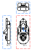
Front, left, right, bottom, top, rear and isometric views.
-
Front, bottom and right views.
-
Front, top and left views.
Clear the Insert drawing in [open product's name]
option if you do not want to insert the drawing in the current product. This
option is selected by default.
Note:
Two types of representations, shared or aggregated, are created depending on the availability of the option Insert drawing in [open product's name].
- Shared representation: If you use any one of the following commands, then the Insert drawing in [open product's name] option is available and selected and the new drawing will be inserted in the product as a shared representation:
- Start
 in the Bar, then select Mechanical > Drafting
- PLM Access > Drawing...
- PLM Access > New... > Drawing
- Aggregated representation: If you use Insert > Drawing command from the contextual menu on the product or the 3D shape, then the option Insert drawing in [open product's name] is not available and, in this case, the drawing will be inserted in the product/3D shape as an aggregated representation.
Click Finish. The View Creation Wizard
dialog box appears. It will disappear as soon as the view creation process
is completed.

|


