Creating a Front View | ||||||||
|
| |||||||
The Tools Palette toolbar appears.
Select Front View
 from the Tools Palette.
 Important: You have to select a planar element only to perform this command.
Select the face as shown.
The View Creation dialog box appears.
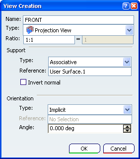
Click OK in the View creation dialog box.
The section cut view is created. Front views are represented by a blue reference axis and are identified as Front View.1 in the Specification Tree.
Tip: When you select an empty view/plane annotation, its normal axis is red colored until you create an annotation.
Right-click the annotation plane in the geometry or in the specification tree and select the Invert Normal contextual menu.
The projection view normal is reversed.
Important: When the view annotation plane is created on an axis system, the Invert Normal command is not available because the view annotation plane takes by default the axis system orientation.