Creating Dimensions and Associated Datums | |||||
|
| ||||
Select the hole edge as shown on the part.
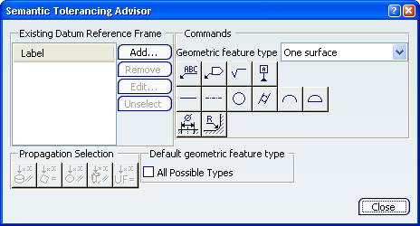
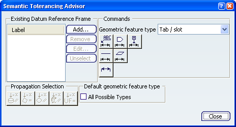
The Semantic Tolerancing Advisor dialog box is updated.
The Limit of Size Definition dialog box appears.
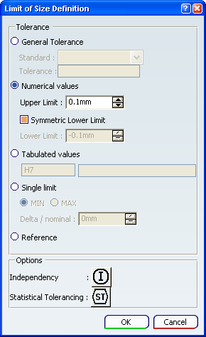
Check that Numerical values is selected, Upper Limit is 0.1mm and Symmetric Lower Limit is selected in the Limit of Size Definition dialog box and click OK.
The dimension is created.

Click Semantic Datum
 (One surface).
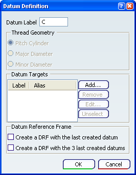
The Datum Definition dialog box appears.
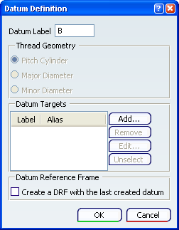
Important: The Thread Geometry frame only appears in ASME Y14.5-2009 standard context.
Click OK in the dialog box.
The datum is added to the dimension.
Select the two hole edges as shown on the part.
The Semantic Tolerancing Advisor dialog box is updated.
Click Distance Creation
 (Tab/Slot):
The Limit of Size Definition dialog box appears.
Check that Numerical values is selected, Upper Limit is 0.1mm and Symmetric Lower Limit is selected in the Limit of Size Definition dialog box and click OK.
The Annotation Creation message box appears.
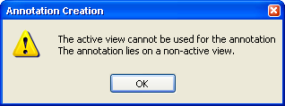
Click OK in the Annotation Creation message box.
The dimension is created.
Click Semantic Datum
 (Tab/Slot).
The Datum Definition dialog box appears.
Click OK in the dialog box.
The datum is added to the dimension.
The dimensions and datum are created in the geometry and specification tree.