Analyzing Using Isophotes | ||||||
|
| |||||
Click Isophotes Mapping Analysis

The Isophote Analysis dialog box is displayed.
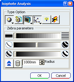
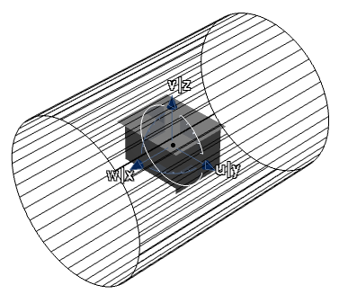
In the Type Option area of the dialog box select Cylindric Mode
 .
.
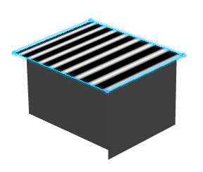
Click a surface in the 3D area.
Isophotes representing cylindrical zebra stripes are applied on the surface.
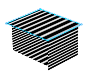
In the Type Option area select Analysis mapping on part
 .
.
Isophotes are displayed on all surfaces of the part, irrespective of whether they are selected or not.
Note: If you want isophotes on all of the part in the 3D area, use this method of global selection rather than using a trap.
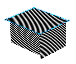
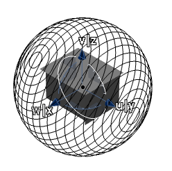
In the Type Option area of the dialog box select Spheric Mode
.
Isophotes representing spherical zebra stripes are applied on the surface.
In the Zebra parameters area select Compass
 .
.
The compass is repositioned at the center of the reference planes and a representation of the spherical 3D manipulator is displayed with its center located at the base of the compass.
In the Type Option area of the dialog box select Cylindric Mode
.
The 3D manipulator changes to a cylindrical shape.
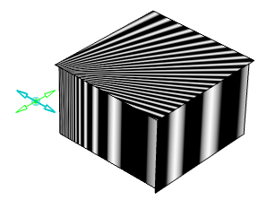
In the Zebra parameters area select Hide the 3D manipulator
 .
.The 3D manipulator disappears, but the compass remains in the 3D area.
Manipulate the compass to modify the orientation of the hidden 3D manipulator.
Because the 3D manipulator orientation has changed, the orientation of the isophotes also changes.
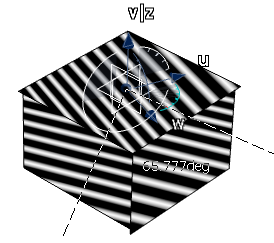
In the Type Option area select User eye
 .
.
Note that Point Mode
 is selected automatically.
- The User eye manipulator appears and it allows you to define another point of view independently from the screen point of view.
- You can move the
Eye User by dragging along its axes or by dragging its
center.
The isophotes mapping is modified according to the Eye User orientation.
Note: If you right-click the Eye user manipulator a contextual menu appears which allows you to Edit its position or Keep this point.