Defining the Fastener Parts of the Engineering Connection Using the Assistant

You can define the fastener parts of the engineering connection for each unitary fastener in a easier and quicker way than the Fastener Connection command.

The assistant provides a list of parts to fasten that is automatically computed. It is based on:

  • the current fastener position in the 3D area,
  • a context (i.e. the parts opened in the current window), and
  • an adjustment variable (i.e. two lengths around the 3D position of the fastener and its normal vector) that defines the limits in which a clash analysis must be processed.

There are several ways to create a fastener connection: while creating or editing a fastener, while creating multiple fasteners (in this case, all created instances share the same joined zones) and while creating an engineering connection.

Related Topics
Creating a Fastener Connection
  1. In the Engineering Connection Definition dialog box, click the Fastening Assistant button.

    The Fastening Assistant dialog box is displayed.

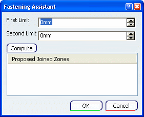
    Two arrows are displayed in the 3D area along the normal vector of the current fastener. These manipulators represent the first and second limit.

  2. Move the manipulators to precisely adjust the limits of the analysis.

  3. Click the Compute button to launch a clash analysis.

    The list of retrieved occurrences of parts is displayed in the bottom frame and the visualization of their associated 3D geometry goes back to the highlight mode. It is therefore easy to identify which parts are to be fastened.

    Note: The Show/No show status is not taken into account, i.e. a part is retrieved even if hidden.

  4. Click OK to close the Fastening Assistant dialog box and go back to the current command.

The fastener parts that are obtained after the computation are automatically added to the fastener engineering connection.