Creating a Cut | ||||
|
| |||
Create a Cut on a Shellable Prism
You can create a cut on a shellable prism.
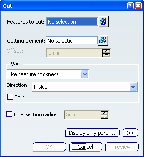
The Cut dialog box appears.
Select the shellable prism as the feature you want to cut.
Tip: If you select several features, the box displays the number of selected elements. To act on this selection, just click the  icon to display the Features to cut dialog
box that allows you to:
icon to display the Features to cut dialog
box that allows you to:- View the selected elements.
- Remove any element clicking the Remove button.
- Replace any element using the Replace button and selecting a new one in the geometry or the specification tree.
Click both arrows on the surfaces to reverse the direction indicating which portion of material is to be kept. The two arrows must point toward the shellable prism as shown here:
Click Preview to see the result.
An offset distance from the selected cutting elements can be entered as an option. Enter 10mm for Offset and click Preview.
Click OK to confirm.
The first cut feature is created. Cut.X is added to the specification tree in the Solid Functional Set.X node. The 3D shape now looks like this:
Just hide both cutting surfaces if you want to see the filleted edges.
![]()
Create a Cut on a Pocket
You can create a cut on a pocket to reshape the pocket.
Click Cut
 .
.From the specification tree, select the extruded surface as the cutting element.
Click OK to confirm the operation and hide all extrusions.
This cut operation has split the pocket while adding some thickness from the edge produced by the cutting surface . The resulting shape looks like this:
Select the Split check box.
The Enter thickness option is selected in the drop down list with 0mm in the value box. All the options in the Wall area are disabled and dimmed. The resulting shape looks like this:
Cut.X is added to the specification tree in the Solid Functional Set.X node.