Click any icon requiring a shape definition. For example,
launch the Shellable Feature
 .
.
Click External Shape
 from any shape feature dialog box. The following dialog box appears:
Select Trim.1 under Geometrical Set.1 from the specification
tree for External Shape.
Enter 0mm for Default offset.
Click OK.
Click Shellable Feature
.
Click External Shape
.
Select Body.2 for External Shape.
Enter 4mm for Default offset.
Enter 6mm for Offset in
Other offset faces to define
the unique offset value to the selected faces.
Select red and green faces for Faces as below.
Select the Apply distance to all selected faces
check box to apply the same offset value to other selected faces.
Click the Fillet tab.
Select Lateral radius to fillet lateral edges.
Set the radius value of your choice.
Select Intersection with Core from the dropdown list to add an intersection fillet.
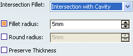
If you want to add material to the feature, select the Fillet radius checkbox, if you want to remove material from the feature, select the Round radius checkbox.
Select the Preserve Thickness checkbox if you want to keep the thickness applied on the feature.
Select Core tab.
The Core capability enables you to define a core body (offset)
for a shellable feature.
Select Select core for Type.
Select Body.2 for Core body.
Enter 1mm for Default offset.
Enter 2mm for Offset in Other offset faces.
Select a green face for Faces.
Click OK.