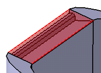
Click Lip
 .
.
The Lip dialog box appears.
Set the Upper/Lower profile method.
You are going to define one lip for Divide.1 and
another lip for Divide.2 (highlighted feature).
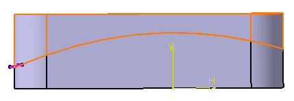
Look more closely at the profiles already sketched:
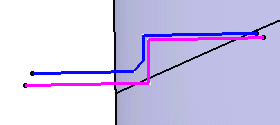
Note that profiles cannot be self-intersecting.
Select Sketch.3 as the upper profile.
Select Sketch.4 as the lower profile.
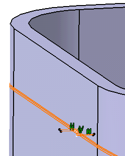
Selecting Protected volume protects the volume
of the lip area by preventing any additional material created by other
features to be added to the lip. For the purpose of our scenario, select
the option.
The lip path consists of edges or curve, planar or non-planar.
All edges must be connected, and the profile plane must intersect a
portion of the path. By default, all split edges constitute the path.
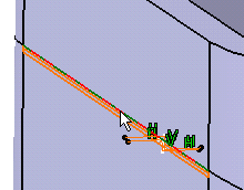
For the purpose of our scenario, deselect the option and select the
edge as shown to restrict the creation of the lips.
Click OK to confirm the operation.
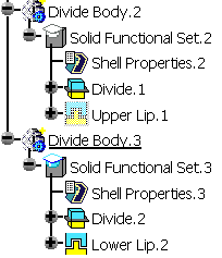
Both lip features Upper Lip.1 and Lower
Lip.2 are added to the specification tree. Each of them is located
in a distinct Divide body.
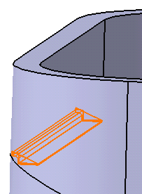
Hide Divide Body.2 to make visualization
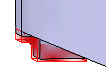
easier. Lower Lip is created only on the selected edge and
the protected area appears in red:
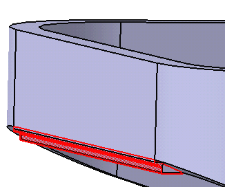
Looking more closely, the shape looks like this:
Show Divide Body .2 and hide Divide
Body.3 to see the second lip.
