Creating a Draft Angle | |||||
|
| ||||
The Draft Definition dialog box appears. An arrow appears on a plane, indicating the default pulling direction.
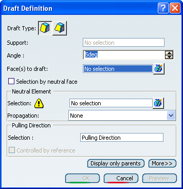
Important: Click  after the Faces to draft box to edit the list of
the faces to be drafted. For more information about that capability,
refer to
Part Design User's Guide: Using Miscellaneous Tools: Editing a List of Elements.
 Select Selection by neutral face to determine the selection mode.
Select the upper face as the neutral element. This selection allows the application to detect the face to be drafted.
The neutral element is now displayed in blue, the neutral curve is in pink. The faces to be drafted are in dark red.
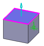
The default angle value is 5. Enter 7 degrees as the new angle value.
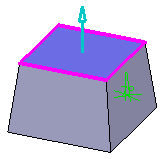
The new angle value is displayed in the geometry.
Click Preview to see the draft to be created.
Click More to access additional options.
To know how to use the options Parting Element and Draft Form, see Drafts with Parting Elements in Part Design User guide.
Click the Limiting Elements box. While drafting a face, you can limit it by selecting one or more faces or planes that intersect it completely.
Select Plane.1 as the limiting element.
The arrow points to the portion of material that will be kept after performing the operation.
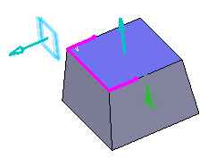
Select Plane.2 as the second limiting element.
Note that the number of limiting elements you select is indicated in the dialog box, just in front of the Limiting Elements box.
Click the arrow to reverse its direction, and therefore retain the opposite side of the feature.
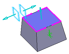
Important: When using several limiting elements, make sure that they do not intersect on the face to be drafted. Click OK to confirm the operation.
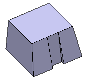
The faces are drafted but the part areas included between both limiting planes have not been modified, as specified through the limiting element option.
