Specification Tree | ||
| ||
Tree Structure
The typical Functional Modeling Part specification tree structure is described in this reference section.
The following picture represents a typical Functional Modeling Part specification tree: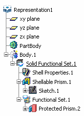
![]()
Symbols
The various symbols used to identify the elements created in the specification tree are described in this reference section.
General
|
|
3D Shape RepresentationBody |
|
Ordered Geometrical Set |
|
|
Solid Functional Set |
|
Sketch |
|
|
Functional Set |
|
Positioned Sketch |
|
|
Geometrical Set |
||
|
|
Body |
|
Solid Bodies (bodies created with application versions up to Version 5 Release 14). |
Depending on the chosen environment type, icons representing bodies (and partbodies) are assigned distinct colors as summarized in this table:
| Environment type | Solid body | Body | Insert Body command |
 |
 |
Solid body |
|
 |
|
Body |
|
For more information, see the Part Design User's Guide
Basic Features
Point |
External Feature |
||
Line Plane |
Core Feature |
||
Plane |
Cutout Feature |
||
Added Feature |
Push Feature |
||
Protected Feature |
Pull Feature |
||
Shellable Feature |
Fitting Feature |
||
Internal Feature |
Dress-up Features and Modifiers
| Cut | Chamfer, local modifier | ||
| Remove | Chamfer | ||
| Intersect | Draft Angle | ||
| Edge Fillet, local modifier | Variable Angle Draft | ||
| Variable Radius Fillet, local modifier | Draft Reflect Line | ||
| Face-Face Fillet, local modifier | Draft Angle, local modifier | ||
| Tritangent Fillet, local modifier | Variable Angle Draft, local modifier | ||
| Chordal Fillet, local modifier | Draft Reflect Line, local modifier | ||
| Edge Fillet | Pattern | ||
| Variable Radius Fillet | Transform | ||
| Face-Face Fillet | Mirror | ||
| Tritangent Fillet | Offset | ||
| Chordal Fillet | Thickness | ||
Power Copy |
Thread/Tap |