Add a Local Mesh Size
Local mesh sizes are local specifications relative to the size
of the elements constituting the finite element mesh.
Click
Local Mesh Size.
The Local Mesh Size dialog box appears.
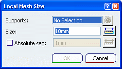
Select the supports.
You can select several geometry supports to apply the local size
to all supports simultaneously. You can apply in sequence several local mesh size specifications
to the system. A separate object will be created for each
specification in the specification tree.
A symbol representing the local size is visualized on the
support as soon as you select it.
Enter a size value in the Size box.
The smallest element size that can be used to generate a mesh is
0.1mm. To avoid geometrical problems in the mesher, the
smallest size of an element is set to 100 times the geometrical
model tolerance. This tolerance is actually set to
0.001mm and cannot be modified whatever the dimension of
the part. This is why the mesh global size must be bigger than
0.1mm.
To add a local sag, select the Absolute sag check box, and enter a sag value. Local mesh sags are local specifications relative to the maximum
distance between the element boundaries and the boundary of the
system. You can use the ruler button on the right of the field to enter
a distance between two supports by selecting them in sequence.
Click OK.
A local size specification appears in the specification tree
under the active mesh.

Add a
Local Edge Distribution
You can specify the number of local nodes you want to distribute on an edge.
Click
Edge Distribution.
The Edge Distribution dialog box appears.
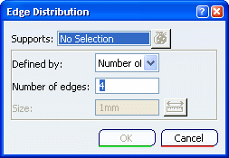
Select the supports.
You can select only curves or faces. If you select a face, the
distribution is applied to all the boundary curves of the face. In the Defined by list, choose the distribution type. Select: - Number of edges to impose a distribution by specifying the number of mesh edges you want.
- Size to impose a distribution by specifying the size. This local specification is used to calculate the nearest
number of edges for each support to approximate the specified size.
If you selected Number of edges, enter the number of mesh edge you want to create in the Number of edges box. If you selected Size, enter a size value.
Click OK. An edge distribution specification is created in the specification tree under a Mesh Specifications set.
Impose Points Locally
You can specify the points that you want to impose, that is to say specify the points to be taken into account when you mesh.
Click Impose Points. The Imposed Points dialog box appears.
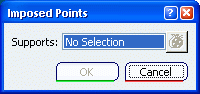
Select the points you want to be imposed. Click OK. An imposed point specification is created in a Mesh Specifications set.
|