Creating a Circular Cutout | |||||
|
| ||||
Create Cutouts from a Point
You can create cutouts from a point.
Click Circular Cutout
 in the Cutting/Stamping toolbar (Holes sub-toolbar).
The Circular cutout definition dialog box opens.
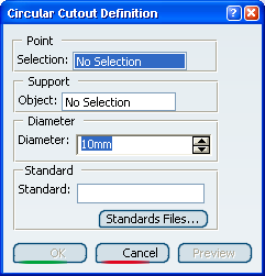
Select the Point that will be the center of the circular cutout.
It can either be a point or several points.
Tips: - The point can be selected anywhere in the geometry, not necessarily on a surface. In that case, an orthogonal projection will be performed.
- You can also directly click the surface: a point will be created under the pointer.
- To deselect a point, click it in the specification tree.
Select the Support object where the circular cutout will be positioned (Wall.xxx for instance).
Tip: The support can be different from the support where the point lies. In that case, an orthogonal projection will be performed. The cutout is previewed with default parameters. 
Click OK to validate.
The circular cutout (identified as circular cutout.xxx) is created and the specification tree is updated accordingly.
Tip: Circular cutouts can be created on the and on bends. For more information on standard files, refer to .
![]()
Create Cutouts from a Sketch
You can create cutouts from a sketch.
Click Circular Cutout
.
The Circular Cutout Definition dialog box opens.
![]()
Create Cutouts from a Mapped Curve
You can create cutouts from a mapped curve.
Click Circular Cutout
.The Circular cutout Definition dialog box opens.
![]()
Create Cutouts from a Projection
You can create cutouts from a projection.
Click Circular Cutout
.
The Circular Cutout Definition dialog box opens.
Click OK to validate.
The circular cutouts (identified as circular cutout.xxx) is created and the specification tree is updated accordingly.
Important: When the profile is not only composed of points, the constituents points of the profile are used to create the cutouts, as well as for the sketch, the mapped curve or the projection.