More About Routing Conductors | |||||
|
| ||||
Supported Devices / Assemblies for Conductor Routing
Electrical conductor routing supports devices (single insert connectors, Shells and Backshells) and assemblies for conductor routing.
Important:
Only Assemblies
connected through the following connection points are supported:
|
The computed conductor length is an addition of the length of Bundle Segment between assemblies plus the values of Extra Length attribute on intermediate devices.
It is possible to route conductors to complex assemblies. Electrical conductor routing algorithm will automatically manage conductor routing to the specified device through the supported complex assemblies:
- Conductors are routed to the terminal device (a Shell or Single Insert Connector (SIC) or Contact) or to the cavity of terminal device of a valid complex assembly.
- It is possible to visualize the conductor's route through complex assemblies using the Link Review tool.
- Realistic value of conductor lengths is computed and stored on conductors after conductor routing.
You can now specify a Shell and a Contact as the termination element for conductor end in a .xml file. The process of defining a Shell and Contact in xml is similar to the one of SIC / Connector.
A contact does not have a cavity though it has a Bundle Connection Point. Therefore the Contact should be mentioned as it is in the .xml file to define one of the conductor termination elements.
It is possible to:
- to define several Backshell connection points to Shells
- to define several Backshell connection points to Equipments
- to define several Bundle Connection Point to Backshells
- to assemble a Shell through its cavity connection point inside another shell cavity (ability to define cavities and cavity connection point on shells).
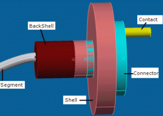
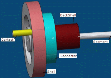
Here are two examples of complex connector assemblies modeled in CATIA:
|
|
|
|
![]()
About Extra Length
Extra length is defined by the cavity of the intermediate and termination devices and/or the cavity of the Backshell is used for conductor length computation.
Extra Length on Backshell can be set while creating the Backshell or by selecting the Properties contextual menu of the Backshell reference.
In case of complex connector assembly, the intermediate device will be taken in to account for conductor length computation by setting the Extra length value on the devices' cavity. This Extra Length on the cavity can be set through Edit > Properties.
Important:
|

