Creating User-defined Restraints | ||||||||
|
| |||||||
In the Restraints toolbar, click User-defined Restraint
 .
.The User-defined Restraint dialog box appears.
Optional: In the Name box, modify the name of the restraint.
Select the support. By default, all the degrees of freedom are fixed up.
Symbols representing fixed degrees of freedom in all restrained directions for the selected geometry are visualized.
Tip: You can select several supports in sequence to apply the specification to all supports simultaneously. Any selectable geometry is highlighted when you pass the cursor over it. See Authorized Supports. Optional: By default, the directions of the degrees of freedom are defined relative to the fixed global axis system (fixed global rectangular coordinate system).
- To define the directions of the degrees of freedom relative to a local variable coordinate system whose type depends on the support geometry, select Implicit in the Type list.
- To define the directions of the degrees of freedom relative to a user-defined coordinate system, select User in the Type list, and select a user axis system in the specification tree. The name of the user axis system is displayed automatically in the Current axis box, and the components of the resultant force are defined relative to the specified rectangular axis system.
Optional: Select the Display locally check box to display locally the axis system.
To fix degrees of freedom select the corresponding check boxes. To release degrees of freedom, clear the corresponding check boxes.
You can fix or release six degrees of freedom per node:
- Translation 1 = Translation in the X-direction
- Translation 2 = Translation in the Y-direction
- Translation 3 = Translation in the Z-direction
- Rotation 1 = Rotation in the X-direction
- Rotation 2 = Rotation in the Y-direction
- Rotation 3 = Rotation in the Z-direction
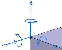
In the following figure, the symbols show that all the degrees of freedom of the selected point have been fixed.

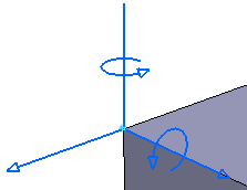
In the following figure, the symbols shows that the translation 3 and rotation 1 have been released.

Important: If you select the Restrain Rotation check boxes, make sure the selected elements can actually be restrained at given rotations. Click OK.
The user-defined restraint is created, and User-defined Restraint.1 appears in the specification tree under the active restraint set.