Creating Retainers | ||||||
|
| |||||
Click Support
 or select Insert > Support...
Select a 3D shape representation in either the specification tree or the geometry area.
The Support Definition dialog box opens:
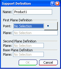
Click OK to validate.
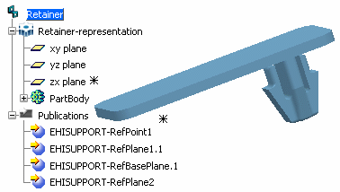
The specification tree is updated:
The publications are created with the specific retainer parameter EHISUPPORT-RefBasePlane.
Tip: You can route flat cables on retainer supports. Flat cables are positioned on supports according to a default reference axis which is perpendicular to the base plane. If you want to change the flat cable's orientation, you can use the Rotate functionality to define a new angle. For more information, please refer to Electrical 3D Installation User's Guide: Working with Segments: Using the Rotate Command on Flat Cables and Electrical 3D Installation User's Guide: Creating Flat Cables: About Orientation Management.