Double-click the 3D shape
representation or a About Electrical Devices in the
specification tree.
The workbench switches to
Electrical Part Design.
Click
Connector
 or
select Insert > Device Behavior > Connector...
The standard 3D shape is automatically detected.
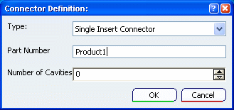
The Connector Definition dialog box opens:

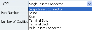
Select the desired connector type in the Type
list:

The different types available are:
- Single Insert
Connector: male or female connector
- Splice:
connector used to secure segments from different geometrical
segments or used between wires belonging to the same segment
- Stud: connector used
to secure segments
- Terminal Strip:
connector with electrical termination strips
- Terminal Block:
connector used to secure segments, each segment conductorbeing
connected to a termination
- Multi Insert Connector: connector mounting
more than one single insert connector
Enter an identifier in the Name box, for
example Connector_M.
Enter the Number of Cavities you want to
add.
Cavities are placed using an axis system whose origin is
located at the origin of the standard 3D shape.
If need be,
you can edit the cavities to reposition them.
Click OK to validate.
The selected part is now an electrical connector.