Adding a Segment Connection Point | |||||
|
| ||||
Add a Segment Connection Point
You can add a segment connection point to a device.
Click Segment Connection Point
 or
select Insert > Connection Point > Segment Connection Point...
or
select Insert > Connection Point > Segment Connection Point...Select the electrical device to which you want to add a segment connection point.
The Segment Connection Point Definition dialog box opens:
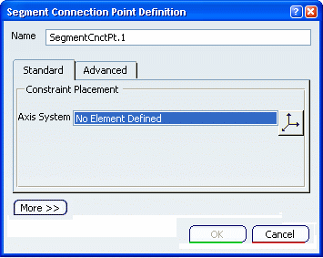
Place the segment connection point using an axis system.
Tip: This is the recommended placement method. - Click
 .
.The Axis System Definition dialog box opens.
If there is an existing representation, a right-handed axis system is positioned by default.
You can also position segment connection points using the Placing Connection Points Using the Advanced Method.
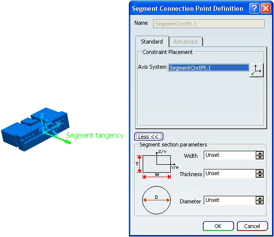
- Click
If you want to create flat cables, you need to define their properties in the Segment Connection Point Definition dialog box.
![]()
Define Segment Section Parameters
Branch dimensions can be defined on the Segment Connection Point. These dimensions are used while routing a branch on this Segment Connection Point, if the Automatically impose profile properties from segment connection point option is checked in the Electrical Geometry Management tab in Tools > Options > Equipment > Electrical Discipline > Electrical Assembly Design. If all the flat cable conditions are complete (for more information, please refer to Electrical 3D Installation User's Guide: Creating Flat Cables: About Flat Cables, you can create a flat cable by routing the branch on the segment connection point.
A flat cable should always have a segment connection point containing the flat cable information, otherwise you will not be able to create a flat cable.
Click More... to define the properties of a flat cable.
Note: For more information about Axis System
, please refer to the Generative Shape Design User's Guide: Using Tools: Defining an Axis System.To manage the flat cables' orientation, it is recommended to use the Standard tab.
Edit the Segment section parameters
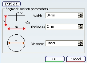
The axis system of the connector's segment connection point is already defined. For a flat cable:
- y: corresponds to the Width of the flat cable's profile.
- z: corresponds to the Thickness.
For more information, please refer to Electrical 3D Installation User's Guide: Creating Flat Cables: About Orientation Management .
By default, a flat cable is rectangular, but if the user chooses to define the Diameter, the result will look like creating a standard branch (it will not be flat). The Diameter is taken into account only when the Width or Thickness is Unset.