Creating and Removing Electrical Dimensions | |||
| |||
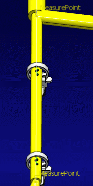
Defining Measure Points
You must select Measure Points on Electrical components before creating dimensions. Measure Points are published geometrical elements allowing you to define the start or end point of an Electrical dimension.
You can use:
- Default Measure Points: you do not need to define the Default Measure Points on Electrical components, they are considered automatically. For example:
- Segment end is a Default Measure Point for segment selection
- Segment Connection Point on devices
- Entry point and Exit plane for supports
- or User-defined Measure Points: If you want to define any other point as Measure Point, then you have to define it before using the commands. And this Measure Point should respect a naming convention: "EhfMeasurePoint_xxx" in which "xxx" can be replaced by user information. For example: a point on curve published as "EhfMeaurePoint_15mmFromEnd" is a User-defined Measure Point. It will be selected if it is nearer to the selection than the segment end.
| Tip: To de-select a Measure Point, click it again. |
![]()
Creating Multiple Dimensions
You can use the Multiple Dimensions command to create one or several dimensions at one shot, depending on the number of Measure Points (Default or User-defined Measure Points) you select. If you select n Measure Points, you will obtain n-1 dimensions. Moreover, as the junction between segments is automatically considered as a Measure Point, a new dimension is created each time a junction is found.
Note: There is an exception when the user's selections are separated with un-selected branches, then the junctions will not be automatically selected as Measure Points, and dimensions will not be created between junctions.
Use the default background to be able to see the dimensions.
Click Multiple Dimensions
 in the Electrical Dimensions toolbar.
The Electrical Dimensions dialog box appears.
Hover the mouse over the different segments to see the available measure points appear.
By default, the available measure points for supports or protections are the entry and exit points. Press Ctrl while hovering over the support or protection to show the middle measure point. If you want this option to be the default option, go to Tools > Options > Equipment > Wire Harness Flattening and select the Measure Point is always the middle of support and protection check box.
Click the different measure points.
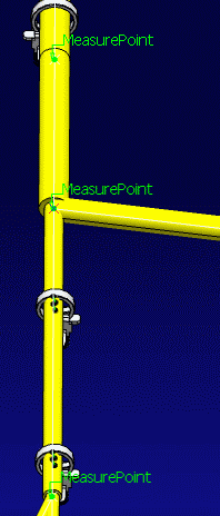
Once selected they turn green.
Important: If the chosen segment is not selectable, a tooltip displays an error message. Click OK in the Electrical Dimensions dialog box to validate and let the dimensions appear.
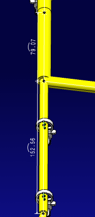
To reposition the dimensions, you can click the annotation and move them up / down or to the right / left.
Note: The dimensions are created inside the Representation, under the nodes Electrical Dimension Set and Annotation Set.1 in the specification tree. The feature called Electrical Dimension stores the specifications of the dimension: the two ends and the path (i.e. list of segments).
![]()
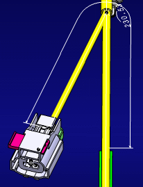
Creating Overall Dimension
You can use the Overall Dimension command to create a dimension on the overall length of several electrical components, a dimension having a start and an end point, taken as a whole.
Use the default background to be able to see the dimensions.
Click Overall Dimension
 in the Electrical Dimensions toolbar.
The Electrical Dimensions dialog box appears.
Click the different measure points.
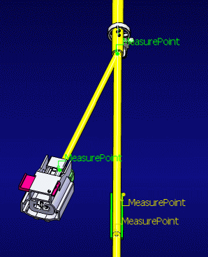
Once selected they turn green.
You just need to select key points, points that intersect with two branches or electrical geometries.
Click OK in the Electrical Dimensions dialog box to validate and let the dimensions appear.
Warning:
|
Note: When the electrical geometry is not flattened, the electrical dimensions are only indicated with start and end points with the overall dimension written on the second point.
![]()
Removing Electrical Dimensions
Multiple Dimensions and Overall Dimension create one Electrical Dimension path for each dimension. If you remove the Electrical Dimension path by using Delete on keyboard, the dimension is removed but the Electrical Dimension path is not removed (cf. steps 1 & 2 below). However, the Remove Electrical Dimension command allows the removal of Electrical Dimension path on deletion of the dimension (cf. step 3).
In Electrical Harness Flatening, as you can perform multiple selections, the Remove Dimensions command works with the Tools Palette. For more information, please refer to Infrastructrure's User Guide: Interface Description: About the Tools Palette.
Or click the Remove Dimensions command
 . The Tools Palette appears, displaying the options and fields associated with this
command.
. The Tools Palette appears, displaying the options and fields associated with this
command.Select the FTA Dimension in the 3D space and the name of the first object you select is displayed in the toolbar:
Click Finish
 to remove all the selected dimensions and the corresponding Electrical path in the specification tree. As long as you do not click this icon and when one representation is active, you can select Electrical Dimensions from other representations in the specification tree, or you can keep on selecting
objects in the 3D (thanks to selection traps). Then, the number of selected elements is displayed in the toolbar instead of the
element's name:
to remove all the selected dimensions and the corresponding Electrical path in the specification tree. As long as you do not click this icon and when one representation is active, you can select Electrical Dimensions from other representations in the specification tree, or you can keep on selecting
objects in the 3D (thanks to selection traps). Then, the number of selected elements is displayed in the toolbar instead of the
element's name:
Thus, the Electrical Dimension in 3D and its linked electrical path feature are removed from the specification tree.The command will terminate with the Finish action.