Creating Constraints via a Dialog Box | ||||||
|
| |||||
Multi-select the elements to be constrained. For example, two lines.
Important: If you want the constraints to be created permanently, activate Dimensional Constraints  and/or Geometric Constraints
 (depending
on the type of constraint you want to create) from the
Sketch tools toolbar. If you do not activate these icons,
the constraints will only be created temporarily.
(depending
on the type of constraint you want to create) from the
Sketch tools toolbar. If you do not activate these icons,
the constraints will only be created temporarily.Click Constraints Defined in Dialog Box
 in the Constraint toolbar.
The Constraint Definition dialog box appears, indicating the types of constraints you can set between the selected lines (selectable options).
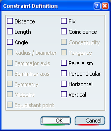
These constraints may be constraints to be applied either one per element (Length, Fix, Horizontal, Vertical) or constraints between two selected elements (Distance, Angle, Coincidence, Parallelism or Perpendicular). Multi-selection is available.
If constraints already exist, they are checked in the dialog box, by default.
Click OK.
The perpendicularity symbol appears:
Select the bottom line and click Constraints Defined in Dialog Box
.The Constraint Definition dialog box appears, indicating that you can set the line as a reference.
Select the Fix check box in the dialog box and click OK.
The anchor symbol appears indicating that the line is defined as a reference.
Select the corner on the left of the profile and click Constraints Defined in Dialog Box
.
The Constraint Definition dialog box appears, indicating that you can choose the Radius/Diameter or Fix option.
Select the Radius/Diameter check box in the Constraint Definition dialog box and click OK.
The radius value appears.
Multi-select both vertical lines and click Constraints Defined in Dialog Box
. The Constraint Definition dialog box appears.
Select the Distance check box in the Constraint Definition dialog box and click OK.
The distance between both lines appears.
Tip: After the constraint was created, you can modify the constraint measure direction and/or reference at any time. For more information, see Defining Measure Directions. Important: By default, a diameter constraint is created on closed circles when checking the Radius/Diameter option. If you need a radius constraint, you just have to convert this constraint into a radius constraint by double-clicking it and choosing the Radius option.