About Geometry Using SmartPick | |||||
|
| ||||
From Scratch
You can create geometrical elements by progressively specifying a given number of characteristic points. These characteristic points can be specified whatever the active Sketcher command. Characteristic points are pre-determined fictitious points managed by SmartPick which allow creating and manipulating geometrical elements whatever the complexity of the latter.
You will create some of these characteristic points with total
freedom (both horizontal and vertical degrees of freedom are
available  ), and others with partial freedom (only
one degree of freedom is available
  ).
).
You will find here below a non-exhaustive list with Sketcher elementary geometrical elements and corresponding characteristic points. SmartPick lets you position these points using one of the following: the cursor, the Sketch tools toolbar, the contextual menu, Shift or Ctrl key.
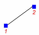
- A line
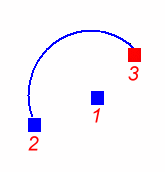
- An arc (center radius)
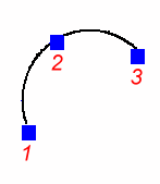
- An arc of a circle using three points
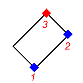
- An oriented rectangle
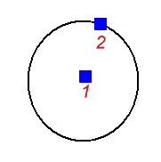
- A circle
- A parabola
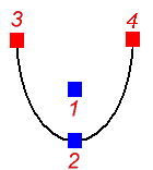
The order in which the above mentioned characteristic points (1, 2,
3, 4) will be specified cannot be modified. Still, you can choose
the means to be used for positioning these points, as long as you
exclusively take into account:
- positioning specifications (SmartPick cursor)
- external geometry (for example, two lines parallel to each others, or two coincident points)
- internal geometry characteristics (horizontal/vertical lines, quarter of arc of circles)
- the externalized parameters of a geometrical element (length, angle, excentricity and so forth)
![]()
According to Existing Geometry
There are a few things that you need to know when using SmartPick with existing geometry.
Reference Geometry
SmartPick finds out geometrical specifications according to geometrical elements that already exist in a sketch.
You will only detect geometrical specifications according to the
current sketch elements that are visible in the 3D window in which
the cursor is positioned. You will not need to perform any
interaction and you will be returned a visual feedback as shown
below in a non exhaustive way:
- Parallel (two lines)
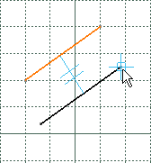
- Tangent (a line and a circle)
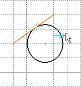
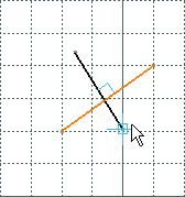
- Perpendicular (two lines)
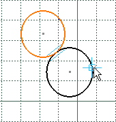
- Tangent (two circles)
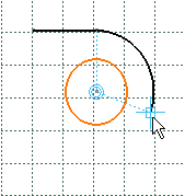
- Concentric (a circle and an arc)
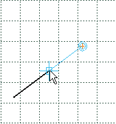
- Parallel (two lines)
| Tip: Consequently, when detecting a constraint, detection can result ambiguous. To remove this ambiguity, you can try to move the viewpoint so that the elements that imply ambiguity would disappear. |
As you will see when using SmartPick, snapping ambiguities currently occur. Besides, the dimensional specifications of a part often depend on technological specifications.
These dimensional specifications are defined as the part is being designed, they depend on the current application area and are, as a result, very hard to guess for the SmartPick tool.
In order to solve these ambiguities, SmartPick classifies possible snapping according to the geometric constraints that are associated to these snapping. As such, a given cursor positioning will be only assigned one snapping. Unfortunately, this classification cannot be modified. It is provided in the table below.
| Constraints Decreasing Priority Order | |
|---|---|
| 1. | Point-to-point coincidence |
| 2. | Point-to-extremity point coincidence |
| 3. | Point-to-noticeable point coincidence (for example, the midpoint of a line) |
| 4. | Curve-to-curve tangency |
| 5. | Horizontal or vertical line, or else a quarter of an arc of a circle |
| 6. | Parallelism |
| 7. | Perpendicular curves |
| 8. | Point-to-curve coincidence |
| 9. | Curve-to-curve coincidence or point to curve support coincidence |
| 10. | Point on a perpendicular line through a line end point |
| 11. | Point at a vertical position |
| 12. | Point at a horizontal position |
Moreover, to remove ambiguity during the creation of elements, the three options which are parallelism, perpendicular and tangency can be activated independently from each other. See SmartPick options in the Customizing section of this guide.
In addition to this classification, when several snappings are possible for a given type of geometric constraints, SmartPick takes into account the distance between the snapped cursor and the geometrical element according to which the snapping is possible. In this case, SmartPick snaps to the nearest element.
Nevertheless, there are some cases when SmartPick does not allow dimensioning as desired without additional interactions. This is why SmartPick manages two means for applying a particular snapping relatively to the geometrical elements.
Forcing the Snapping
SmartPick allows forcing the snapping on a given geometrical
element using either:
- the contextual menu or
- the Ctrl key
SmartPick allows forcing the snapping on a given geometrical
element using the contextual menu. You will avoid ambiguities
linked to the automatic detection of elements in the current 3D
viewpoint by forcing:
snapping detected at a distance: parallel, perpendicular, concentric, tangency and curve (line/circle) that goes through a point.
At a distance means that these constraints are detected even though the cursor is not positioned on the reference element.
snapping at a given position that is relative to a geometrical element: line midpoint, circle center.
At a given position means that both degrees of freedom are locked.
The contextual menu is therefore available when right-clicking most
Sketcher geometrical elements. Of course, the contents of the
contextual menu depends of the element that is being currently
created. This contextual menu can be made of the below four
sub-parts:
- Option that belongs to the Base Infrastructure product.
- Snapping the characteristic point that is being manipulated (see From scratch paragraph and table below).
- Snapping the geometrical element that is being created (see table below).
- Managing the parameters that are associated to the geometrical
element that is being sketched.
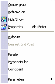
Any snapping that is imposed via the contextual menu can be deactivated. To do this, right-click in the 3D window background and select Reset.
The table below lists the constraints that can be detected when snapping characteristic points which are being manipulated, relatively to existing geometrical elements, and thanks to the contextual menu.
| Popped-up Geometry | Available Snapping |
|---|---|
| Line | Line midpoint |
| Circle | Circle center |
| Ellipse | Ellipse center |
| Curve | Nearest end point |
The table below indicates the possible snapping for geometrical elements which are being created, relatively to existing geometry and thanks to the contextual menu.
| Element currently created | ||||
| External Geometry => | Point | Line | Ellipse | |
| Point |  |
 |
  |
|
| Line | Midpoint Nearest end point |    |
 |
|
| Circle | Center Nearest end point |   |
  |
|
| Ellipse | Center Nearest end point |   |
No | |
| Conic | No |   |
No | |
| Spline | No |   |
No |
In the example below, you can see the various snapping possibilities for a line that is being created (dotted lines in the example) relatively to the existing spline: 3 tangency possibilities and 2 perpendicularity possibilities. The point you right-click to display the contextual menu is used to determine which option will be offered in the contextual menu. So depending on where you click, you will not be offered the same options.
Note that the software takes into account what has already been specified (in this example, the first point of the line) to offer the various snapping options. For this reason, depending on the first point of the geometrical element that is being created, there may be cases in which no solution can be found or in which the solution offered does not correspond to what you want. In such a case, try to right-click before and/or after the point you want the software to choose. If you try both ways, one solution at least should be found.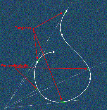
SmartPick also allows forcing the current snapping on an element
using the Ctrl key:
- You can force SmartPick to remain snapped on an element whatever the position of the cursor. In order to do this, press the Ctrl key while the geometrical snapping you want to force is active (the element may be highlighted and symbols may appear). Keep the Ctrl key pressed.
- This functionality is efficient if once the Ctrl key is pressed you can still move the cursor. In other words, Ctrl has no effect if the current snapping inhibits both degrees of freedom. This is often the case when given snapping combinations are possible (for example at the intersection of two lines) or when the cursor is close to a given point (explicit or implicit as for example the midpoint of a segment).
- The Ctrl key is very useful when the sketch includes
many geometrical elements because SmartPick takes into account the
distance between the cursor and the geometrical element.
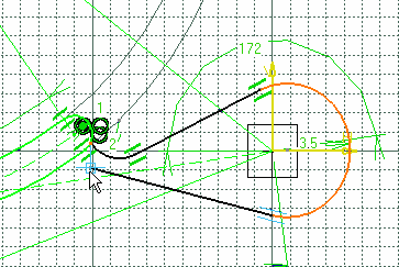
- This is the zone in which the line-circle tangency snapping (due to
the circle proximity) has the first priority.
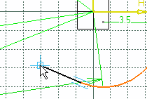
Apart from this zone, either the tangency snapping is meaningless or it interferes with closest geometries or still with possible constraints that are assigned higher priorities (see table).
If SmartPick cannot solve an ambiguity and returns a snapping that you are not satisfied with, you can de-activate SmartPick assistant by pressing the Shift key.
| Warning: It can happen that either the Shift or Ctrl key do not behave as specified in the paragraphs above. In fact, sometimes the viewer loses the focus (selection priority). You can then perform a local transformation to recover the focus: use the middle mouse button and manipulate the viewpoint. You will thus recover the focus. |
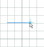
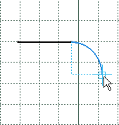
Certain geometrical elements are assigned internal peculiar
geometrical characteristics. For example and as shown below, this
is the case for horizontal/vertical lines and for quarters of arcs
of circles. When such an internal specification is found out by
SmartPick, the color of the currently created geometrical element
becomes blue.
![]()
Managing Geometry Parameters
SmartPick also manages internal geometrical specifications such as a line length or a circle radius.
Indeed, these specifications (further called parameters) decrease available degrees of freedom of a geometry characteristic point (see previous From Scratch paragraph). All these parameters are accessed through the Sketch tools toolbar which gathers all the available parameters that can be valuated for a given geometry creation command. Finally, while the SmartPick cursor moves, the Sketch tools toolbar displays the parameters value.
Listed below are examples of the possible fields of Sketch tools toolbar parameter section:
| Fields | Explanation |
|---|---|
 |
Length and Angle to H axis are available for Line creation command. |
 |
Excentricity is available for Hyperbola creation command. |
| Important: Note that it is always possible to reset a parameter that has been valuated in the Sketch tools toolbar. To do this, use contextual sub-menu Reset option that is available on 3D viewer background. |
Relation Between Parameters and Characteristic Points
There is a strong relation between the characteristic point of a geometrical element and some of the parameters it supports. In fact, if a parameter value is modified by moving the cursor, it means that the parameter is linked to the current characteristic point and consequently validating the point will modify the parameter status.
Indeed, as when valuated a characteristic point can no longer be modified, associated parameters get frozen which is echoed by a grayed entry in the Sketch tools toolbar.
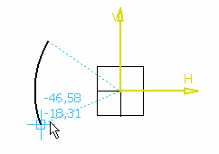
As an example, in Arc Circle creation command, when the
arc start point is defined (at the sketch origin on this picture)
both Radius and Start Angle to H Axis get frozen. Indeed, as the
arc center is necessarily previously defined, to impose arc start
point leaves no ambiguity on the radius and the start angle of the
sector.

Specific Parameters
Some parameters have a specific behavior. This behavior is common to all geometry creation commands that use these parameters. This is the case for Angle and Sector parameters.
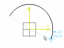
Sector Parameter :This parameter is oriented so that no ambiguity is possible when
defining an angular sector. In the standard units system, an angle
range is from -360 to 360deg. Any other value is recomputed to this
range. Positive values are for direct sectors (you go from the
start direction to the end one the same way you go from H axis to V
axis). Negative values are on the other end for reverse arcs (you
go from the start direction to the end one the same way you go from
V axis to H axis).
- A direct angular sector
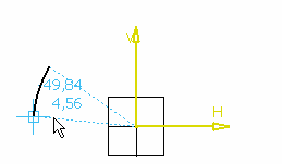

- A reverse angular sector

| Important: Note that an angular sector cannot be identically equal to zero. |
The angle parameter is also oriented, its range is from 0 to 360 deg. As a consequence, a -10 deg value is identically equivalent to a 350 deg value and a 0 deg value is definitely not equal to a 180 deg value.
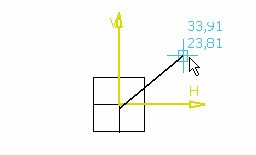

A fixed 30 deg angle value imposed to a line
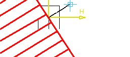

| Important: Note that an angular sector cannot be identically equal to zero. Note that when this angle is fixed, the cursor position is restricted to the half of the sketch plane. Otherwise a 30 deg angle would be equal to a 210 deg one which is excluded. |
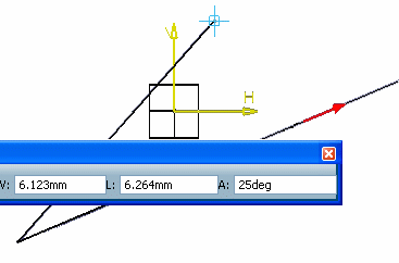
By default, angle values are computed relatively to H Axis. This can be modified any time you want to define an angle value using the Parameters > Set as Angle Reference contextual command.
When an angle value is available in the Sketch tools
toolbar, any line that is contained in the current sketch can be
defined as the angle computation basis. To issue out orientation, a
red arrow is displayed to show the reference line orientation. In
this example, a 25 deg angle is set relatively to an existing line.
It is possible to copy some of the parameters values from any existing geometrical element that can be defined with the same parameters. The Copy functionality is available through the contextual menu Parameter section for length and radius parameters.
Length can be copied from a line while radius from a circle or an arc.