Using Tools for Sketching | ||||
|
| |||
Grid
You can click Grid
![]() to display a grid in a session. The grid size can be decided as per the requirement, there is no definite rule.
to display a grid in a session. The grid size can be decided as per the requirement, there is no definite rule.
The grid spacing and graduations are defined using the Tools > Options > Mechanical > Sketcher > Grid area. For more information, see Sketcher (Customizing).
![]()
Snap to Point
You can click Snap to Point
![]() to make your sketch begin or end on the points of the grid. As you are sketching
the points are snapped to the intersection points of the grid.
to make your sketch begin or end on the points of the grid. As you are sketching
the points are snapped to the intersection points of the grid.
Note that this option is also available via Tools > Options > Mechanical > Sketcher > Sketcher tab. For more information, see Sketcher (Customizing).
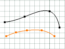
In the following example, the black spline was created with Snap to Point on. The points are on the grid. Conversely, the highlighted spline was created with Snap to Point deactivated.

Important:
|
![]()
Construction/Standard Elements
You can create two types of elements: standard elements and construction elements.
If standard elements represent the most commonly created elements, on some occasions, you will have to create a geometry just to facilitate your design. Construction elements aim at helping you in sketching the required profile.
Click Construction/Standard Element
![]() in the Sketch tools toolbar so that the elements you are now
going to create be either standard or construction element.
As construction elements are not taken into account when creating features,
they do not appear outside the Sketcher.
in the Sketch tools toolbar so that the elements you are now
going to create be either standard or construction element.
As construction elements are not taken into account when creating features,
they do not appear outside the Sketcher.
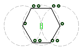
Here is an example of the use of both types of elements.
The hexagon was sketched using three construction circles:
This type of sketch simplifies the creation and the ways in which it is constrained. Setting a radius constraint on the second circle is enough to constrain the whole hexagon.
| Important: The construction elements are automatically removed when they are not used anymore. |
- Standard or Construction Points
Points are represented either by crosses or just by points, depending on the chosen creation mode.
- In standard mode, which is the default mode, points created on a line, for instance, are represented by crosses. The points and the line are visible outside the Sketcher workbench.
- Points generated by Break
 are created in construction mode, even if Standard/Construction
 is set to Standard.
![]()
Geometric Constraints
When selected, Geometric Constraint
![]() enforces the integrity of the geometry between one or more elements.
enforces the integrity of the geometry between one or more elements.
The constraints created are permanent.
![]()
Dimensional Constraints
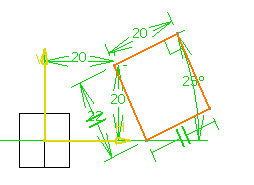
When selected, Dimensional Constraint
![]() enforces the integrity of the dimensions of one or more profile type elements
provided you use the value boxes in the Sketch tools toolbar
for creating this profile.
enforces the integrity of the dimensions of one or more profile type elements
provided you use the value boxes in the Sketch tools toolbar
for creating this profile.
To know more about sketcher constraints, see Setting Constraints, and Infrastructure user's guide (Customization Settings).

![]()
Value Boxes
The values of the elements you sketch appear in the Sketch tools toolbar as you move the pointer over the graphics area. In other words, as you are moving the pointer, the different boxes, for example horizontal (H) and vertical (V) boxes for creating the centre of a circle, display the coordinates corresponding to the pointer position.

You can:
-
Select the desired box of the Sketch tools toolbar and type in the required values.
Note: You can use the Tab key to select the desired box.
-
Increment or decrement the value in a box using the Up Arrow or Down Arrow key according to the grid options.
-
Press Enter to validate your values.
Important:
|