The Finite Element Method | ||
| ||
Finite elements
Predicting how a physical or thermal load will affect a complex part is an extremely difficult task. However, predicting how a load will affect a small, simple part—such as a tiny block—is much easier. The finite element method is based on this assumption: by treating a large, complex part as a collection of small, interconnected, simple pieces, you can predict the response of each simple part and see how it impacts adjacent simple parts.
In DesignSight the large part is broken down into small tetrahedrons. Each of these tetrahedrons is called an element; points along the edges and corners of the tetrahedrons are called nodes.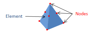
![]()
Meshing and remeshing
The process of splitting a complex part into elements is called meshing; the resulting collection of elements is called a finite element model. A typical finite element model in DesignSight can contain anywhere from thousands to millions of elements.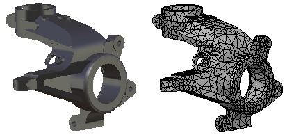
The smaller an element, the easier it is to predict its response. However, when you reduce the element size, more elements are required to fill the geometry of a part. A finite element model with very small elements yields the most accurate results, but the simulation takes longer because it must predict the response of more elements.
DesignSight automatically meshes your part when you perform a simulation. Initially, the elements throughout the finite element model are of roughly uniform size. However, if your settings are configured to request more accurate results (see Accuracy Settings), your part may be remeshed at the end of a simulation. The remeshing uses smaller elements in regions that have potentially inaccurate results. A new simulation is run with the new finite element model; the smaller elements produce more accurate results than the original finite element model.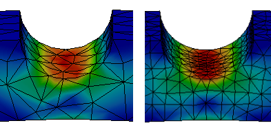
In some cases the original finite element model provides sufficiently accurate results given the levels of stress or deformation in the simulation; in these cases remeshing is not required.
The finite element model created by DesignSight is associated with a simulation object and is also added to the original product structure as a representation. This representation should not be used in other types of simulations (in the Structural Analysis workbench, for example).
![]()
Materials
The material that you apply to your part is also applied to each element in the finite element model. The material determines the stiffness and/or conductivity of the element and how it will respond under a load. Complex material characteristics such as plasticity are accounted for in each individual element.
![]()
Restraints and loads
Although you apply restraints and loads on the original geometry of your part, they are actually transferred to the nodes of the associated finite element model.
Restraints constrain the motion of a node in a particular direction during the simulation. In the simplest case—a clamp—the nodes are not allowed to move at all. In more complicated cases, such as with ball joints, the nodes are allowed to move only along a predefined direction or path.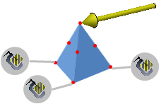
Loads are also applied to the nodes in your finite element model. Within any given element, the load on the node causes the element to deform slightly. While the deformation of a single element is relatively straightforward, the node on one element is usually also connected to an adjacent element. The simulation must consider how the deformation of one element affects the deformation of any adjacent elements, and so on.
![]()
Thermal conditions
Thermal conditions are also applied to the underlying elements in your part. As heat flows into or out of the element, the conductivity of the element determines how the heat propagates; the temperatures at the nodes are calculated accordingly. As with physical loads, the nodal temperatures in one element directly affect the temperature of nodes in adjacent elements.
![]()
Solution increments
The power of simulation lies in the ability to account for the various loads and responses in connected elements. The simulation is complete when an equilibrium has been established between the external loads and temperatures and the internal responses within the finite element model.
In some cases, it is not possible to determine a solution based on the full load (whether physical or thermal); local changes or responses may be too significant to establish an equilibrium for the entire part. In such situations, the simulation employs an incremental approach. A portion of the load is applied, then the response of the entire part is determined. Once equilibrium has been established at the partial load, additional loading is applied, and a new equilibrium is determined.
For stress simulations, the incremental physical loading is directly related to how stopping criteria are assessed (see General Options). Each time an equilibrium state is achieved, DesignSight checks the plastic strain in the model; if the specified stopping criterion is exceeded anywhere, the simulation is ended at the current equilibirum configuration. DesignSight is not able to determine the exact point at which the stopping criterion was exceeded; it can check only during periodic states of equilibrium. A simulation may also exceed the stopping criterion and run to completion: if it is possible to establish equilibrium initially under the full loading, the solution will be determined without ever checking the stopping criterion.