Mapping Blocks | |||
| |||
Map Ports and Signals
You can map ports and signals and define the style and color of the link.
Click Add Mapping
 in the Block Tools toolbar then select the
two ports to connect.
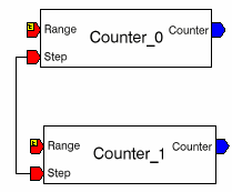
 In this example, select the Step port of instance Counter_0 and Step port of instance Counter_1.
A link is created between these two ports.
Note:
- To cancel the mapping after the selection of the starting point, click Esc twice.
- Add Mapping is disabled as soon as the mapping is done.
- To do several mappings without having to activate the command each time, double-click Add Mapping.
- This command is also available between two signals, a port and a signal.
Important: : If you map two ports with incompatible types, a dotted red line is created. A tool tip associated to the line indicates the cause of the error. Double-click the mapping to see the linking line properties.
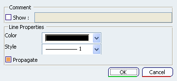
The following options are available:- Comment: You can add a comment to the mapping. If the check box is selected, the comment will be displayed in the Block Editor.
- Color: You can change the color of the linking line by filling this field.
- Type: You can change the style of the linking line by filling this field.
- Propagate: If you change the color of the line, the color of all the other lines connected to the same ports or signals are changed.
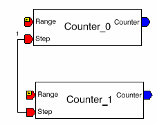
Select Show, add a comment, and click OK.
![]()
Create a New Mapped Port
The Map to New Port command allows you to create a new port mapped to an existing port.
Right-click the port Step of instance Counter_0 and select Map To New Port.
A new port is created and mapped to the Step port.
Note that the direction (input) and the type (any number) of the instance ports are automatically propagated to the block port.
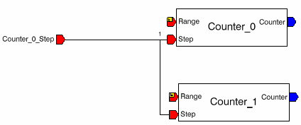
Double-click the new port to change its parameters. The Block Definition dialog box appears.
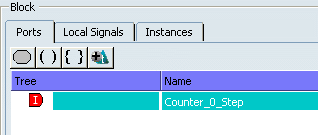
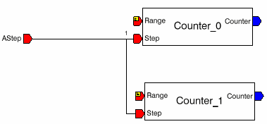
Change the name to AStep and click OK. The new name is displayed in the Block Editor.
![]()
Convert Mapping to Label
A mapping can be represented by a link or a label.
Select the two lines and select Selected object > Change Into Label in the contextual menu.
The Label Properties dialog box is displayed.
Change the name of the label to aStep.
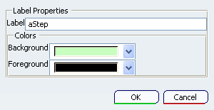
Name: You can change the name of the label.
Background: You can change the background color of the label.
Foreground: You can change the foreground color of the label.
Click OK. The two lines are converted to labels.
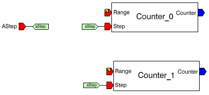
Note: To access the Label Properties dialog box, double-click a label.
Click a label to see the mapping between the same labels represented by a dotted line.
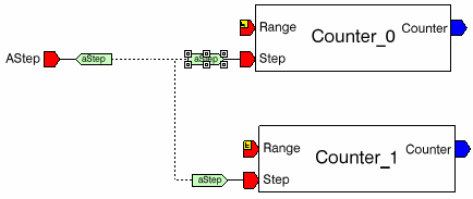
Note: Labels can be created directly using Add Label Mapping

in the Block Tools toolbar.
![]()
Create Signals Mapped to Ports
The Map to New Signal command allows you to create a signal mapped to an existing port.
Right-click a Range port and select Map to New Signal.
Note: By moving over the signal, you can see its name and type.
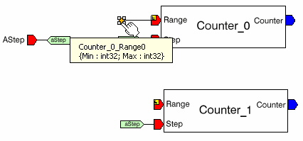
To change the name of the signal, double-click on it or select Counter_0_Range0 object > Definition in the contextual menu.
The Block Definition dialog box is opened at the Local Signals tab.

Change the name and click OK.
![]()
Expand Ports
The Expand Port command allows you to access the element of a structured port or a tuple.
Right-click the port Range of instance Counter_1, and select Map To New Port. A new structured port is created.

Select Expand Port
 in the contextual menu of Range.
 Note: This command expands the type of the port. The elements of the structure appear in the Block Editor enabling you to map each component.

The ports Range and Counter_1_Range are expanded. Note that the mapping is not done at root level but at element level.
Click
 (or select Expand Port
 in the contextual menu). The port Counter_1_Range
is expanded.
Click
 (or select Collapse Port
 in the contextual menu) for each port. The components
of the structure are hidden.
in the contextual menu) for each port. The components
of the structure are hidden.Select Shrink Port
 in
the contextual menu of Range. The ports are now mapped
at the root of the structure.
Note: If a port is mapped to the same structured port, you are recommended to connect the ports at the root level. If an element of the structure is added or removed, the change will be automatically managed by the typing mechanism. If the elements of the structure are mapped one by one, you must manually manage modifications to the structure.
Repeat step 2 to expand the ports again.
Delete the mapping between the elements of the structure.

Select one of the ports and select Add Mapping
 .
.
The elements of the structure are mapped.

Note: The inference mechanism re-computes the type and direction of the port Counter_1_Range. The direction of the element Max is undefined and its type is 'any.
Right-click one of the ports and select Shrink.
A warning message appears.

Note: As the mapping between the ports Range and Counter_1_Range is partial, the mapping cannot be done at root level (as seen in step 5). So in this case, the mapping is disconnected. This deletion breaks the inference mechanism (type and direction) between the two ports. The type of Counter_1_Range is set to 'any (that is, the elements of the structure are deleted) and the direction is undefined.
Click Yes to continue.

Delete the remaining connections.
Note: If the option Remove links when an object is removed (see Block Editor in the Customizing section) is checked, the remaining connection is automatically deleted.