Set up the appropriate hardware configuration.
Set up the graphic adaptor configuration for stereoscopic
display.
This step depends on
hardware and operating system configuration. Some systems require
administrator privileges to change the graphic adaptor display
mode.
You are required to determine the height, width and
frequency characteristics of the graphic interface.
Start a session.
Select .
Select the Enables stereoscopic display option.
Exit the session to save your settings, then restart.
Load a model.

Select .

Click the arrow to display the whole toolbar.

For more information about the different anaglyph stereoscopic effects, see More About Stereoscopic Viewing.
In the Immersive Virtuality toolbar, select the stereoscopic mode of your choice. In this scenario,  Active or Passive Stereoscopic Effects is selected.
Stereoscopic viewing is enabled and has the following impacts on the application window:
- The view is switched to a perspective view.
- The 2D mouse cursor is replaced by a 3D immersive cursor to avoid perception conflicts and keep the stereoscopic effect.
- The Robot and the Compass are hidden.

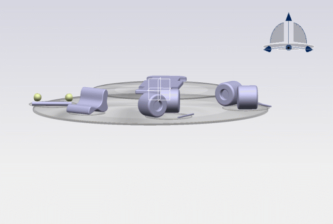
This immersive cursor  is made of two concentric circles: a small one filled in black and a larger one with no fill color. The circles are displayed on each end user's eye (which is why you can see two pair of concentric circles in the picture above) and their depth is based on the depth of the object the cursor is snapped to.
The distance between the two pairs of concentric circles is based on the inter-eye distance and the depth of the underlying object. For instance, when both pairs are merged into one, it means that the immersive cursor is snapped to an object located in the screen plane.
Optional: For an optimized visualization, you can:
- Press F3 to remove the specification tree.
- Select then deactivate the Preselect in geometry view option.
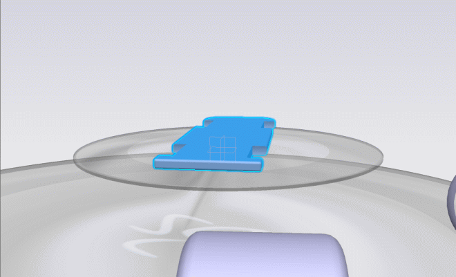
Set the object of your choice in the screen plane by right-clicking it in the 3D window then selecting Reframe On.
In the picture below, the object highlighted in blue has been set in the screen plane and is centered in the application window:

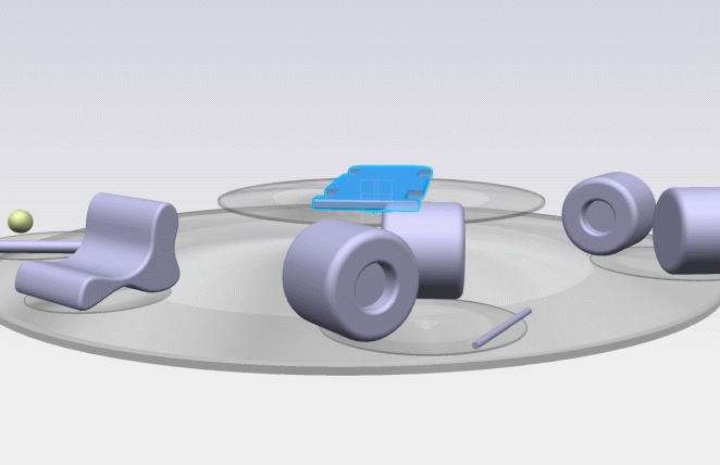
Zoom out to view the whole scene.

- Any objects located in front of the screen plane will have a smaller depth and thus, will have a 3D pop-out effect.
- Any objects located behind the screen plane will have a larger depth.
Move the immersive cursor over the objects.
The immersive cursor is rendered using a furtive technique: when the cursor is moved, only the two circles are rendered and not the whole scene to enhance the rendering time. This is why the color of the cursor matches the one of the underlying object.
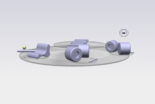
As the distance between the two pairs of circle depends on the inter-eye distance, the look of the cursor varies according to the object you point at. In the pictures below, you can see that as we get closer to the center of the screen, the concentric circles get closer to each other:
To exit stereoscopic viewing, select  No Stereoscopic Effects.