Kinematics Mechanism Design File-based Design Import | ||
| ||
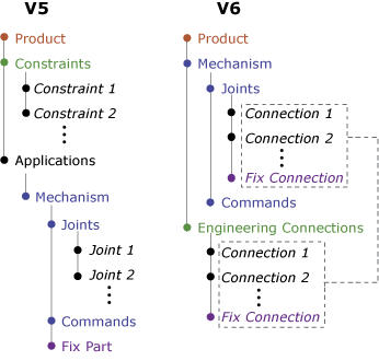
In V5 a mechanism consists of joints, commands, and a fixed part; the mechanism joints are distinct from assembly constraints in the associated product. In V6 both mechanism joints and assembly constraints are derived from common engineering connections in the product (see ).
When importing a V5 product that includes a mechanism, a V6 product and associated mechanism representation are created. Joints in the V5 mechanism are defined as engineering connections in the V6 product; these engineering connections are also included in the mechanism representation.
V5 commands are imported as controlled constraints in the V6 engineering connections; commands based on these controlled constraints are created in the V6
mechanism representation. An axis system is generated
in the V6 model to support the controlled constraints for the
command.
Mechanisms that work in V5 may not work after being imported into V6. The sections below describe some common problems, as well as possible solutions. You should complete the following general steps before attempting to simulate a V5 mechanism in V6:
- Review and clean the mechanism in V5 using the CATDUA utility.
- Update and save the cleaned mechanism in V5.
- Import the V5 mechanism into V6.
- Perform a PLM Update.
| Version 5 | Version 6 |
|---|---|
| Mechanisms | |
| Mechanism | Imported as mechanism representation |
| Imported submechanism | Imported as mechanism representation |
| Commands | |
| Command | Imported |
| Joints | |
| Rigid | Imported as Rigid engineering connection
See Rigid connections between multiple products for limitations on this type of joint. |
| Prismatic | Imported as Prismatic engineering connection |
| Revolute | Imported as Revolute engineering connection |
| Spherical | Imported as Spherical engineering connection |
| Cylindrical | Imported as Cylindrical engineering connection |
| Planar | Imported as Planar engineering connection |
| U Joint | Imported as Universal engineering connection |
| Point Curve | Imported as Point Curve engineering connection
The imported Point Curve engineering connection is always based on a curvilinear constraint, regardless of the constraint types that were used to define the V5 joint. |
| Point Surface | Imported as Point Surface engineering connection |
| Roll Curve | Imported as Roll Curve engineering connection |
| Slide Curve | Imported as Slide Curve engineering connection |
| Gear | Imported as Gear engineering connection and two Revolute engineering connections; the Gear connection couples the two Revolute connections |
| Rack | Imported as Rack engineering connection, Prismatic engineering connection, and Revolute engineering connection; the Rack connection couples the Prismatic and Revolute connections |
| Cable | Imported as Cable engineering connection and two Prismatic engineering connections; the Cable connection couples the two Prismatic connections |
| Screw | Imported as Screw engineering connection |
| CV Joint | Imported as two Universal engineering connections |
| Axis-Based Joint | Imported as appropriate engineering connection and an axis system |
| Fixed Parts | |
| Fixed Part | Imported as Fix engineering connection
A Fix engineering connection is always created for imported mechanisms. If the V5 mechanism does not include a fixed part, the V6 Fix engineering connection will not be associated with any product; you must associate the Fix with a product before simulating the mechanism. |
| Dressup | |
| Dressup | Imported as Rigid engineering connection |
Importing Mechanisms in Asynchronous Mode
Asynchronous migration allows you to update a previously imported mechanism in V6 with changes that were made in V5. For details about using asynchronous migration, see File- based Design Import User's Guide:Importing V5 Data by using Mapping Tables.
The following modifications to a V5 mechanism can be propagated to an existing V6 mechanism using asynchronous migration:
- Create/delete a mechanism
- Simulate a mechanism
- Create/delete a joint
- Modify the ratio of a joint
- Modify the limits of a joint
- Create/delete/rename a command
- Delete the Fixed Part
| Warning: Any modifications to the mechanism that are made in V6 are lost when you perform an asynchronous migration; the updated mechanism is based entirely on the contents of the current V5 mechanism. |
The name of the imported mechanism is always based on the mechanism name at the time of the original import. If you rename the mechanism in V5 or V6, the original name is restored on the V6 mechanism when you perform an asynchronous migration.
![]()
Broken Joints
If the supporting constraints or geometries have been deleted from a V5 joint, the joint will be broken when it is imported into V6.
File-based design import attempts to repair broken
joints during the import. The repair process may create new constraints (for deleted
constraints) or new axis systems (for missing geometry) in the V6
model. The following types of
joints can be repaired:
- Rigid
- Prismatic
- Revolute
- Spherical
- Cylindrical
- Planar
- Fixed
- Compound (gear, rack and cable)
The repair process may fail in some situations. Situations that could cause the repair process to fail include
- if the geometry of the mechanism is not imported into V6,
- if the underlying geometry for the V5 joint constraints is not appropriate for the associated V6 engineering connections, or
- if the initial value of the V5 joint command is outside of the V6 controlled constraint limits,
- if a sub-joint that belongs to a V5 compound joint (gear, rack or cable) has been deleted.
If the repair process fails, the V6 mechanism is incomplete and cannot be simulated. The settings on the dialog box for the Assembly Design workbench determine how broken joints are handled during import: they can be imported and deactivated, imported and kept active, or not imported (see Engineering connection in the Assembly Design User's Guide for more information).
If broken joints are imported into your V6 mechanism, they must be repaired manually. Performing a PLM Update (after activating the broken joints if necessary) can provide diagnostic and error messages concerning the problems with the broken joints.
![]()
Limits
If a V5 joint command uses the default value limits (-100 to 100 for length-based commands, -360° to 360° for angle-based commands), no limits are assigned to the controlled constraint in the V6 engineering connection. When simulating an imported mechanism without limits, the default limits based on the initial constraint values are enforced in the Kinematics Simulation player.
If nondefault limits are defined for a V5 joint command, these limits are imported into the controlled constraint in the V6 engineering connection.
If a V5 mechanism is not updated prior to import, it is possible for the nominal value of a command to be outside of the defined command limits. During import, the nominal value is reset in the V6 mechanism to either the maximum limit value (if the nominal value was above the limit range) or minimum limit value (if the nominal value was below the limit range).
In V5, command limits are not enforced during a mechanism simulation; for example, a Revolute joint with an upper limit of 360° may continue to rotate past 360° during a simulation. The command limits are enforced during a mechanism simulation in V6. Therefore, a mechanism simulation that appears to work in V5 may not work in V6 because the upper or lower command limits are reached during the simulation. Removing or redefining the command limits in the V6 mechanism typically resolves this problem.
![]()
Rigid Connections between Multiple Products
In some cases a rigid joint (in V5) or engineering connection (in V6) is based on a single Fix Together constraint. In V5, the Fix Together constraint can be used to attach multiple products to each other; in V6, the Fix Together constraint can be used to attach only two products to each other. If a V5 rigid joint fixes together more than two products, only two of those products will be fixed together in the imported V6 rigid engineering connection. The two products are chosen based on the two products referenced in the name of the V5 rigid joint.
![]()
Duplicate Joints
In V5 two mechanism representations within a single product may include identical joint definitions. In V6 these joints are combined into a single engineering connection at the product level; modifications to this engineering connection are reflected in both mechanism representations.
Similar V5 joints are not combined in V6 if any of the following
conditions exist:
- The products involved in the joints are different.
- The joint types are different.
- The number or types of coincidence constraints in the joint definitions are not identical.
- The support geometries in the joint definitions are not identical.
Duplicate joints often appear when compound connections are "chained" together. For example, a mechanism involving three sequentially enmeshed gears typically requires the definition of two gear connections: one to link the first gear to the second gear, and another to link the second gear to the third gear. In V5 a unique revolute joint must be created for use in each gear joint definition, resulting in two identical revolute joints on the second gear. V6 does not require unique engineering connections for each compound connection; the same engineering connection can be used in multiple compound connections. When this mechanism is imported from V5 to V6, the duplicate revolute joint is removed and a single revolute engineering connection is used in both gear engineering connection definitions.
![]()
Imported Submechanisms
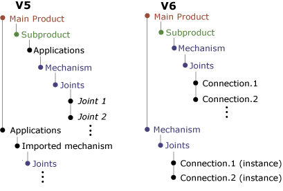
In V5 it is possible to define a mechanism for a product (Product B), then instance this product within another product (Product A). You can subsequently define another mechanism for Product A based on the geometry and joints in Product B. This second mechanism is called an "imported" mechanism; the original mechanism and the imported mechanism are identical, but they are instanced at different levels in the product structure. In this situation, Product B is flexible (or made flexible at first simulation).
These "imported" mechanisms in the V5 product are supported by file-based design import. In V6, product B remains fexible, the created engineering connections are instanced under Product A and included in the mechansim representation.
![]()
Dressup
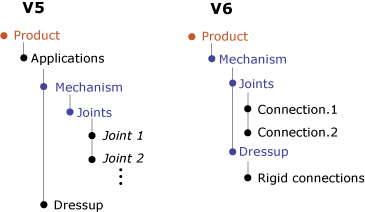
In V5 with dressup function it is possible to attach one or several parts to a given moving part involved in the mechanism. You can subsequently include parts that are not involved in the mechanism in the kinematics simulation. When importing a V5 dressup to V6, rigid engineering connections between the mechanism and the dressup are created. Dressup is defined as rigid engineering connections in the
V6 product; these engineering connections are included in the
mechanism representation.