Select PLM Access >
Mechanical product... to create a product and associated 3D
shape representation. Double-click the 3D Shape representation. Switch to Circuit Board Design if not already
in this workbench.
Click Panel
 . .
Panel behavior is added to the mechanical product. Draw the outline of the panel.
To do so:
- Click Sketch
 . .
- Select the xy plane.
The Sketcher workbench is launched.
- Click Profile
 . .
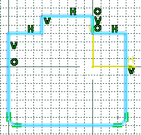
- Sketch the contour of the panel.

For more
information about sketching profiles, refer to
Sketcher User's Guide: Sketching Simple Profiles.
Note: You can also use a 3D curve for the panel contour.
However, if you want to export the panel, you must define an
axis system. For more information, see
Export.
- Click Exit
 workbench to exit Sketcher and return to Circuit Board Design. workbench to exit Sketcher and return to Circuit Board Design.
Create the shape for the panel.
To do so:
- Click
Pad
 . .
The Pad Definition dialog box appears.
-
Enter 2mm in the Length box.
-
Click OK.
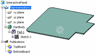
The pad turns sea green in color; the panel shape
has been created. Two publications (TopBoard
and BottomBoard) are added to the specification tree.
The top or the board corresponds to the first limit of the pad
you created to represent the board.

By default, CATIA recognizes the
first pad created as a panel.
|