Editing Constraints in Engineering Connection from 3D | |||||
|
| ||||
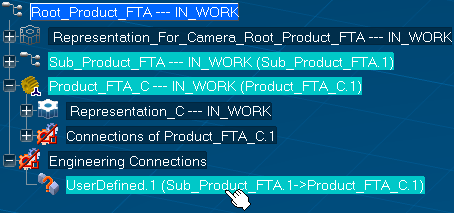
Select an engineering connection from the specification tree.
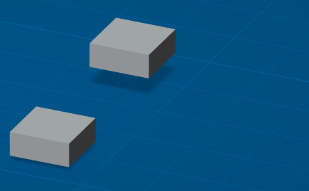
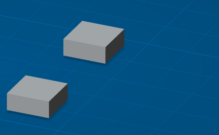
The engineering connection is displayed in 3D.
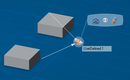
Click Edit constraints
 select .
Tip: You edit directly constraints by right-clicking from the specification tree.
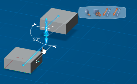
In our example, an offset and an angle constraints are displayed.
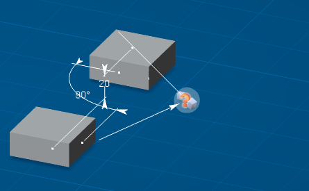
Pass the cursor over the offset constraint.
Important: The manipulator appears with respect of engineering connection definition and indicates in which direction the movable component will move. When both components can be moved, two manipulators appears.
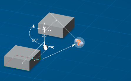
A manipulator appears at one extremity of the offset arrow. You can drag it in order to modify the offset.
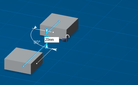
Click the offset value in order to modify it with the keyboard.
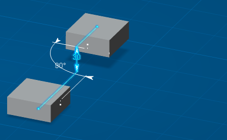
Set the value offset to 30 mm and press Enter.
Click the offset dimension or extension line in order to display the balloon.
Pass the cursor over the left balloon icon.
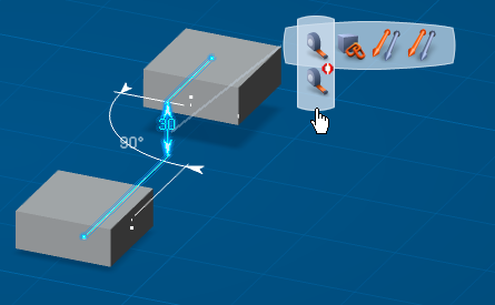
This displays available balloon commands for constraint activation.
Click outside constraints in order to exit the edition mode.