Smart Move | |||||||
|
| ||||||
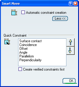
Click Smart Move icon
 and click More>> the Smart Move
dialog box that appears.
and click More>> the Smart Move
dialog box that appears.The Quick Constraint frame contains the list of the constraints that can be set. This list displays these constraints in a hierarchical order and can be edited by using both arrows to right of the dialog box.
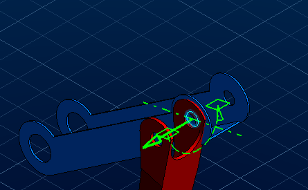
Select the axis of Jack_Branch_1 as shown:
Important: In an flexible assembly, the first select component must be repositionable.
Select the axis of Jack_Branch_3.
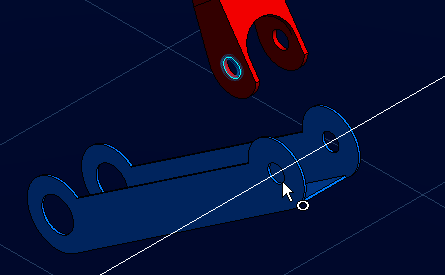
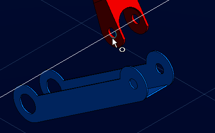
Instead of explicitly selecting both axes, you can select the axis of Jack_Branch_1 and then drop it onto the blue inner cylinder face when your cursor points to this face.The application detects a possible constraint between the axes. As the option Create constraint is on, the application can set a coincidence constraint between both axes.
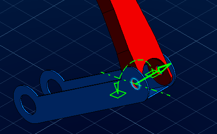
Click the green arrow to reverse the direction of the component.