Smart Move with Viewer | |||||||
|
| ||||||
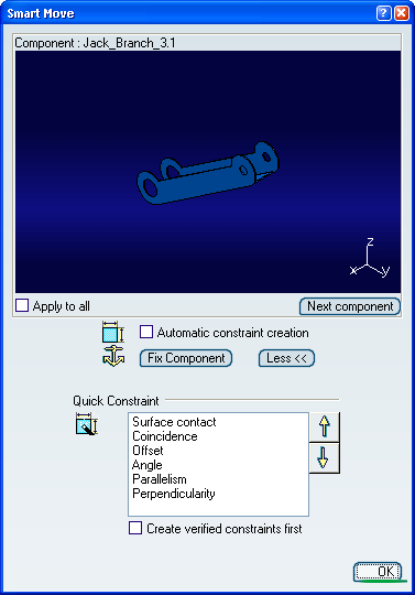
Click Smart Move icon
 and expand the Smart Move
dialog box, including the viewer that appears.
and expand the Smart Move
dialog box, including the viewer that appears.- The Viewer frame: this window appears only if you pre-select the components affected to perform the smart move. These components must belong to the same parent component. Using the viewer allows you to select with more accuracy the geometrical element to be moved and constrained. In the viewer window you can move and rotate the component regardless of its position the geometry window. The viewer do not forbid the selection of the geometrical element in the geometry window.
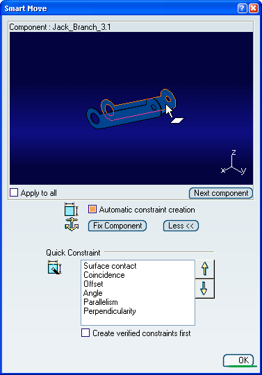
- The Automatic constraint creation option allows you to create constraints to keep the move operation.
- The Fix Component command allows you to prevent the current component from moving from its parents during the update operation.
- The Quick Constraint frame contains the list of the constraints that can be set. This list displays these constraints in a hierarchical order and can be edited by using both arrows to right of the dialog box.
Select the face of Jack_Branch_3 as shown in the dialog box.
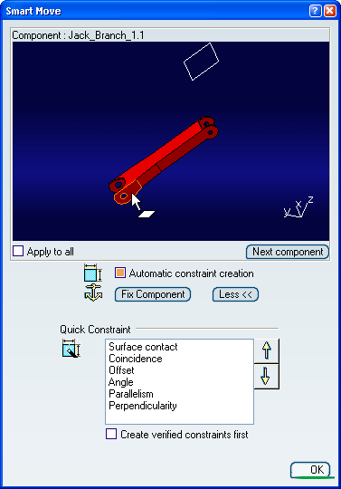
Select the face of Jack_Branch_1 as shown in the dialog box.
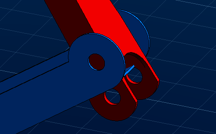
The engineering connection is created and contains a contact constraint.