Analyzing Degrees of Freedom

You can analyze if you need to set additional constraints to the components making up your assembly.

Important: The degrees of freedom analysis is performed from assembly constraints only. This is mean that constraints from design in context or assembly pattern are not taken into account. The analysis is performed from the active component and its child components set, but you must know that:

  • Selecting of any sub-component of a child component returns the analysis of this child component relative to its active parent component only. If you want to analyze the sub-component relative to a child component, activate the child component before.
  • Flexible child components (and their flexible sub-components) of the active component are not taken into account for the analysis. In this case, the analysis is performed from the first rigid sub-component found in the selection, under the active component.

Translations can be performed in a plane is represented by two vectors. These vectors define the translation plane but depending on the geometry, they can constitute an orthonormal system or not. In other words, a planar translation which normal to the plane has the coordinates (x=0, y=1, z=0) can sometimes be represented by:


  • These two vectors:


    • vector 1: x=0, 707107, y=0, z=0,707107

    • vector 2: x=-0, 707107, y=0, z=-0, 707107

  • or by these ones:


    • vector 1: x=1, y=0, z=0

    • vector 2: x=-0, y=0, z=1


Before you begin: Open an assembly.
Related Topics
Defining a Multi-Instantiation
  1. Click the Update All in order to update the assembly.

  2. Right-click Jack_Screw.1 and select the Analyze > Degrees of Freedom from the contextual menu.

    The Degrees of Freedom Analysis dialog box appears.


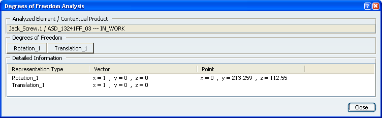
    • The dialog box displays all rotations and translations that remain possible for the selected component. In our scenario, you can rotate ack_Screw (Jack_Screw.1 ) in two ways or translate it in one way.
    • If you look at the geometry, you can notice that these rotations and translations are represented in yellow.

  3. Click the Rotation_2 button.

    The graphic element representing this possible rotation is now highlighted in the geometry for easy identification.


    As detailed in the dialog box, you can perform a rotation around the vector which coordinates are x=1, y=0 and z=0 and using the point with coordinates x=0, y=-213.259 and z=112.55 as the rotation center.

  4. Click the Translation_2 button.

    The graphic element representing this possible rotation is now highlighted too.


    As detailed in the dialog box, you can perform a translation along the vector which coordinates are x=1, y=0 and z=-0.

  5. Click Close to exit the command.