Click Create Grid  in the Grid Tool toolbar.
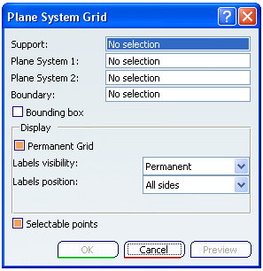
The Plane System Grid dialog box appears.

Select a support in the Support box.
- Select a plane in the 3-D session or specifications tree.
- Select a planar structural object in the 3-D session or specifications tree.
- Right-click in the Support box and select Select Reference Plane.
The Plane System 1 and Plane System 2 boxes display the plane systems based on your selection. These plane systems are perpendicular and complementary to each other.
Select a surface or a volume in the 3-D session, to limit the grid.
Clear the Bounding box check box to define the boundary.
Your selection is displayed in the Boundary box.
Uncheck the Permanent Grid check box from Display area to make the grid visible only in normal view.
In the Labels Visibility list,
- Select Permanent to make the text visible at all times.
- Select Only in Normal View to make the text visible only in normal view.
- Select None to hide the text.
In the Labels Position list,
- Select All Sides to position the text on all sides.
- Select Bottom/Left to position the text Only at the bottom/left.
Select Selectable Points check box to select points at the intersection of grid lines.
You can now select points to place an object on the grid.
Click OK to see the grid.
