Display | ||
| ||
Display in Specification Tree
This section describes the various options available in the Display In Specification Tree area.
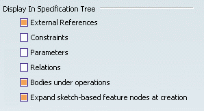
There are six types of elements you can display or not in the specification tree. If you want them to be displayed, just select them.
- External References
- Constraints
- Parameters
- Relations
- Bodies under operations
- Expand sketch-based feature nodes at creation
External References
Copies with links of geometry from other documents:

![]() By default, this option is selected.
By default, this option is selected.
Constraints
Dimensional and geometrical constraints created in the document:

![]() By default, this option is not selected.
By default, this option is not selected.
Parameters
Parameters created using the Knowledge Advisor capability:

If you wish to know what parameters and relations are, see the CATIA
Knowledge Advisor Users Guide.
![]() By default, this option is not selected.
By default, this option is not selected.
Relations
Relations (formulas) created using the Knowledge Advisor capability:

If you wish to know what relations are, see the CATIA Knowledge Advisor
Users Guide.
![]() By default, this option is not selected.
By default, this option is not selected.
Bodies under operations
Bodies attached to other bodies in different ways (via Add, Assemble, Remove, Intersect, Union Trim operations). The option is selected:
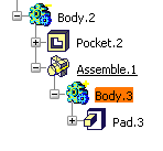
The option is not selected:
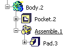
This option is available only with Part Design application. For more, see "Associating Bodies" in the CATIA Part Design Users Guide.
![]() By default, this option is selected.
By default, this option is selected.
Expand sketch-based feature nodes at creation
If the Expand sketch-based feature nodes at creation option is selected, sketch-based features nodes are expanded so as to display sketch nodes. If not selected, sketch nodes are present in the tree but you need to click the plus sign to the left of features to expand them.
![]() By default, this option is selected.
By default, this option is selected.
![]()
Display in Geometry Area
This section describes the various options available in the Display In Geometry Area area.
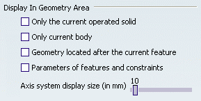
There are five options available for customizing the geometry display:
- Only the current operated solid
- Only current body
- Geometry located after the current feature
- Parameters of features and constraints
- Axis system display size
Only the current operated solid
This option is used when editing features belonging to attachedbodies (bodies that underwent Boolean operations) only. It displays
- only the features of the current body,
- all the other bodies and geometrical sets directly aggregated to the 3D shape.
In the following example, the option is on: you can see Body.2 and Set.1.
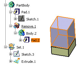
This setting can greatly improve the application
performance whenever you edit these features.
Note: Instead of accessing this option via Tools > Options,
you can click Only in Current Body![]() in the Tools toolbar.
in the Tools toolbar.
![]() By default, this option is not selected.
By default, this option is not selected.
Only Current Body
This option displays the geometry of the current part body or open body only. In the example above, we could not see Set.1.
It is available in Design Mode only.
![]() By default, this option is not selected.
By default, this option is not selected.
Geometry located after the current feature
This option is reserved for Ordered Geometrical Sets (OGSs) and bodies that can include both Part Design features and GSD features (for more information, see Hybrid Design in the CATIA Part Design Users Guide). If selected, the application displays:
- the geometry of the current feature and
- only the GSD and wireframe geometry located after the current feature.
In the example below, since the option is on, you cannot see EdgeFillet.1 nor Hole.1 in the geometry area:
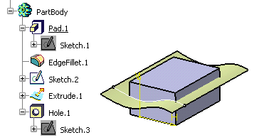
![]() By default, this option is not selected.
By default, this option is not selected.
![]()
Checking Operation When Renaming
This section describes the various options available in the Checking Operation When Renaming area.

Three options let you define rules for renaming geometric elements (using the Properties command).
No name check
Use this option if you wish to allow all types of rename operations whatever the locations of the elements in the specification tree.
| Warning: This option is inefficient for geometric elements renamed by using the engineering knowledge language. |
![]() By default, this option is selected.
By default, this option is selected.
Under the same tree node
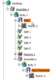
Check this option to prevent two elements belonging to a common node from having the same name. If you are giving an identical name, a warning message is issued informing you that the element you are renaming will be suffixed as 'Renamed'. The check operation in case-insensitive.
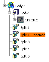
![]() By default, this option is not selected.
By default, this option is not selected.
