View Creation | ||
| ||
View Visualization

- Hide in 3D
-
Select this check box if you want newly created views to be hidden from the 3D window.
Important: You can show or hide the view in the 3D window at any time by right-clicking it in the 2D window and selecting Visualization > Show in 3D or Visualization > Hide in 3D respectively.  By default,
this option is not selected.
By default,
this option is not selected.
![]()
View Background
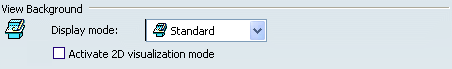
- Display mode
-
From the drop-down list, select a display mode to specify how the 2D and 3D backgrounds should be visualized for newly created views. The options available are described in the table below.
Display mode Description  Standard
Shows both the 2D and 3D backgrounds.  Invisible
Hides both the 2D background (the 3D representation of 2D elements which do not belong to the current view, but to other views) and the 3D background (the representation of all 3D elements, including edges, faces and 3D wireframe).  Unpickable
Prevents from selecting elements in both the 2D and 3D backgrounds, even though you can see them. You can just handle 2D elements which belong to the current view.  Low-intensified
Dims all elements in both the 2D and 3D backgrounds.  Unpickable low-intensified
Dims all elements in both the 2D and 3D backgrounds. Additionally, although you can see these elements, you cannot select them. You can just handle 2D elements in the current view.
By default,
the Standard display mode is selected. - Activate 2D visualization mode
-
Select this check box if you want to display only the 2D planar elements that are in the same plane as this view in 3D for the newly created views.
By default,
this option is not selected.
![]()
Filter
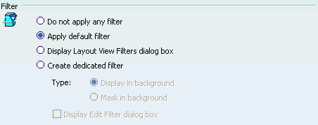
Note: For more information on filters, refer to Creating View Filters.
- Do not apply any filter
Select this option if you want each newly created view to be created without any filter applied to it.
By default,
this option is not selected.- Apply default filter
-
Select this option if you want each newly created view to be filtered by the first layout filter in the list of view filters (available in the Layout View Filters dialog box). By default, this filter is the Default filter (a Mask filter created at the same time as the layout).
By default,
this option is selected. - Display Layout View Filters dialog box
-
Select this option if you want the Layout View Filters dialog box to be displayed each time you create a new view.
By default,
this option is not selected. - Create dedicated filters
-
Select this option if you want a new filter to be created and applied to each newly created view.
Selecting this option makes the options below it available.
By default,
this option is not selected. - Display in background
-
This option is available when the Created dedicated filters option is selected.
Select this option if you want the new filter that is created for each new view to be of the Display type.
By default,
this option is selected. - Mask in background
-
This option is available when the Created dedicated filters option is selected.
Select this option if you want the new filter that is created for each new view to be of the Mask type.
By default,
this option is not selected. - Display Edit Filter dialog box
-
This option is available when the Created dedicated filters option is selected.
Select this option if you want to launch the edition of the new filter automatically.
By default,
this option is not selected.
![]()
Clipping frame

- Activate
-
Select this check box if you want to activate the clipping frame on newly created views using a rectangular frame. The clipping is reframed on the view background (which can be the 3D shape or assembly containing the 2D layout). Refer to Using the Clipping Frame for more information.
By default,
this check box is not selected.
![]()
Clipping outline
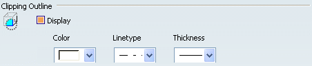
- Display
-
Select this check box if you want to display the outline of the clipping view. Refer to Using the Clipping View for more information.
By default,
this check box is selected. - Color
-
Select a color for boundaries.
By default,
the white color is selected. - Line type
-
Select a line type for boundaries (only among the first height linetypes).
By default,
type 4 is selected. - Thickness
-
Select a line thickness for boundaries.
By default,
index 4 is selected.
![]()
Back Clipping Plane
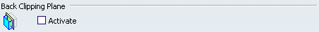
- Activate
-
Select this check box if you want to clip the 2D and 3D backgrounds of newly created views using a back clipping plane. Refer to Using the Back Clipping Plane for more information.
By default,
this check box is not selected.
![]()
Primary View
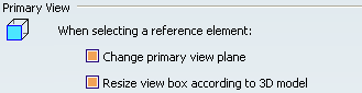
- When selecting a reference element: Change primary view plane
- Select this check box to change the primary view plane during view creation.
- When selecting a reference element: Resize view box according to 3D model
- Select this check box to resize the view bounding box according to 3D model.
By default,
both
the check boxes are selected.
![]()
Multi-planes Section View Boundaries
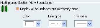
- Display all boundaries but extremity ones
-
Select this check box if you want all the boundaries in newly-created multi-plane section views to be displayed by default. Only the first and last boundary of the first and last sub-view respectively will not be displayed.
By default,
this check box is selected. - Color
-
Select a color for boundaries.
By default,
the white color is selected. - Line type
-
Select a line type for boundaries.
By default,
type 4 is selected. - Thickness
-
Select a line thickness for boundaries.
By default,
index 1 is selected.
![]()
Callout creation
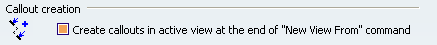
- Create callouts in active view at the end of "New View From" command
-
Select this check box if you want to create callouts in active view at the end of New View From command.
This enables you to create a callout when creating an auxiliary view, a section cut or a section view (including multi-plane section views) from a 3D plane, face or sketch, using the New View From command. The created view is activated at the end of the command.
Notes:
- If several section cut or section views are created at the same time, callouts are created for only those views whose support plane is normal to the support plane of the active view.
- If the active view is not compatible for the callout creation, no callout is created. However, it is possible to add callouts in compatible views after the New View From command using the Create Callout in Reference View command. For more information, refer to 2D Layout for 3D Design User's Guide: Creating Callouts in Reference Views.
- If you do not want the automatic callout creation, you can clear the Create callouts in active view at the end of "New View From" command check box.
By default,
this check box is selected.