STEP | ||
| ||
General
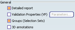
- Detailed report
- When selected, includes the Detailed report this
chapter in the report file.
 By default,
Detailed report is selected.
By default,
Detailed report is selected.
- Validation Properties (VP)
-
Note: In the Data Exchange Interfaces User's Guide read:
- About Validation Properties
- License Requirements for STEP
Once you have activated this option, Validation Properties (VP) become active and Parameters becomes available. It starts the Parameters for Validation Properties dialog box:
In this dialog box, you can:
- activate Geometric Validation Properties (GVP) or Assembly Validation Properties (AVP) according to your needs,
- activate the Clouds of points (COPS) functionality (This functionality involves a slight performance loss, due to the properties computation cost.)
- define the tolerances for the validation properties checking.
Tolerances for Geometric Validation Properties checking detect large errors during exchanges by comparing the centre of gravity, the volume and the area of the exchanged solids with their native properties:
- Volume and area max. Deviation
is a percentage of variation of volume or area allowed.
By default,
the value is set to
1%.
- Centre of gravity max. Deviation
is the maximum error for the center of gravity.
By default,
the value is set to 1m.
SAG for COPS creation density controls the density of the cloud of points generated for each face; the cloud of point is created by tessellating the face according to the given SAG: a low value of SAG means a large number of points by face and a high value of SAG means few points by face. The SAG must be defined between 0.01 and 10.
By default,
the value is set to 0.1
mm.Tolerance for COPS deviation is the largest allowed gap between a point and the imported face. With a standard scale, the deviation must be defined between the following bounds 0.0001 and 0.1.
By default,
the value is set to is 0.01
mm.Default Values reverts to the default values.
By default,
- the option Validation Properties (VP) is not selected.
- In the Parameters dialog box:
- Volume and area max. Deviation is 1,
- Centre of gravity max. Deviation is 1 mm
- the option Cloud of points (COPS) is not selected.
- SAG for COPS creation density is 0.1 mm.
- Tolerance for COPS deviation is 0.01 mm.
- the option Geometric Validation Properties (GVP) is selected.
- the option Assembly Validation Properties (AVP) is not selected.
- Groups (Selection Sets)
-
When this check box is selected:
- at import, Groups found in the STEP file are translated into Selection Sets.
- at export, Selection Sets found in the V6 file are
exported as Groups in the STEP file.
Refer to the STEP: Export chapter for more information (Miscellaneous section).
Note: Importing or exporting Groups may be time consuming.
By default,
Groups (Selection Sets) is selected. - 3D Annotations
-
Note: In the Data Exchange Interfaces User's Guide read:
- About 3D Annotations
- License Requirements for STEP. In addition to those requirements, this functionality requires Application Protocol AP203 ed2 (it follows the recommended Practices for Geometric Dimensions & Tolerances (GD&T) for Polyline Representation.
When selected, this option enables the import and export of 3D annotations. Information about the annotations is found in the report file.
By default,
3D Annotations is not selected.
![]()
Import - Continuity optimization of curves and surfaces
This setting allows a better user control over the number of
curves and surfaces that are created during the process of
importing STEP data into V6:
- V6 requires its geometry to be C2-continuous. When non C2-continuous geometry must be imported from a STEP file, this geometry (curves, surfaces) is broken down into a set of contiguous geometries, each of them being C2-continuous. This is what happens when the No Optimization option is chosen.
- However, this can produce an increase of the size of the resulting data, because more curves/surfaces are created. In order to limit this drawback, two other modes are optionally offered.
- In those modes, the STEP interface tries to limit the splitting of curves and surfaces by modifying their shape slightly, so that they become C2-continuous while remaining very close to their original shape.
- In order to guarantee that the deformation is not excessive, a maximum deviation (tolerance) parameter is used. When in Automatic optimization mode, this maximum deviation is read into the STEP file itself, in the STEP parameter that documents the precision of points in the file. In this mode, the value read from the STEP file is then corrected so that it remains comprised between 10E-2 and 10E-3. This guarantees an optimization that remains compatible with the precision for the data that was set by the emitting system.
- Last, if this strategy is not enough, you can choose the Advanced optimization mode, in which an arbitrary deviation value can be entered.
Select the desired option:
- Automatic optimization
This option proposes no approximation, thus it does not create a significant deformation and keeps the internal BSpline structure (equations and knots).
A continuity optimization is performed within the deformation tolerance used for optimizing BSplines, comprised between 0.001mm and 0.01mm (depending on the tolerance value defined within the imported STEP file) on:
- BSpline surfaces,
- BSpline boundary curves (3D and P-curves when available),
- BSpline independent 3D curves,
The parameters box cannot be activated.
This option softens the effect C2 cutting of faces and boundaries (which is mandatory in V6) without any significant geometric deformation
- Advanced optimization
- No approximation is performed. The internal BSpline structure (equations and knots) is kept. A continuity optimization is performed on:
- BSpline surfaces,
- BSpline boundary curves (3D and P-curves when available),
- BSpline independent 3D curves,
but the deformation tolerance is set by the user. With this option, you can enter a larger tolerance value which may enhance the optimization impact (resulting in less C2 cutting on faces).
- No optimization
-
No optimization is performed on BSplines (neither curves nor surfaces).
Elements are cut at discontinuity points to suit the modeler (exact mathematic continuity). This may result in a dramatic number of faces and boundary curves, data of poor quality and poor performances in further use in V6.
By default,
Automatic optimization is selected. - Parameters
- When Advanced optimization is selected, Parameters gives access to advanced optimization options and tolerances.
Deformation: maximum deformation (in millimeter) allowed in the optimization of curves and surfaces. Ranges between 0.005 and 0.1 mm.Important: the tolerance is shared by the optimization process (in all cases), the Curves and surfaces approximation and the topological reduction of boundaries if you have selected those check boxes. For example, the deformation tolerance is 0.001mm and Curves and surfaces approximation is selected. The tolerance for the optimization is be 50%, i.e. 0.0005mm and that of the Curves and surfaces approximation is also be 50%. Thus, the number of cuts of the faces will vary according to the value entered, and according to the number of check boxes selected.
Angle: angle (in degree) below which contiguous elements can be merged. Ranges between 0 and 10 degrees.
By default,
Deformation is set to 0.003.
Default Value reverts to the default values.
By default,
Angle is set to 2.Curves and surfaces approximation: BSpline surfaces and curves continuity is optimized.
In addition, Bspline curves and surfaces approximation is performed.
It is possible to enter a user value for Deformation.
This option may change the internal structure of BSplines (equations and knots).
This option usually results in a significant decrease in the number of faces cuttings.
By default,
Curves and surfaces
approximation is not selected.
![]()
Export
- Application Protocol (AP)
-
Lets you select the STEP format into which the data will be
exported.
For more information about AP203, AP203 with extensions, AP203 ed2, AP214 and AP214 ed3, refer to Reference Information for STEP.
By default,
Application Protocol (AP) is set to AP203 iso.
- Units
-
Lets you decide whether the data will be exported in mm or inches,
independently of the session unit.
By default,
Units is set to mm.
- Show/NoShow
-
The data to export may be:
- visible entities placed in the Show space,
- hidden entities placed in the NoShow space.
- hidden entities placed in layers that are not visualized.
Note: Visualization filters are taken into account.
By default,
entities placed in non-visualized layers are not exported.When Export also NoShow entities is not selected, only visible entities are exported to STEP.
When Export also NoShow entities is selected, all entities belonging to both the "Show" and the "NoShow" spaces are exported, the entities that are in the NoShow space being exported under the INVISIBILITY STEP entity.
When Export non-visualized layers is selected, all entities belonging to those layers are also exported. Those entities are not exported under the INVISIBILITY STEP entity.
Important: STEP export does not manage the visibility of instances of products. Hence, if an assembly contains instances in No Show: - if all instances are in No Show, those instances and the corresponding product are not exported,
- if at least one instance is visible, the product is exported together with all its instances.
By default,
Export also NoShow entities nor Export also non-visualized layers are selected. - Header of the STEP file
- Defines opens the Define Header of STEP File dialog box to help you define this header:
- Assemblies
-
Lets you select the required export mode for assemblies.
Note: In the Data Exchange Interfaces User's Guide read:
- License Requirements for STEP. In addition to those requirements, One STEP file is available for all Application Protocols while External references to STEP, Global nested assembly and Partial nested assembly are available for AP214 and AP203 ed2 as stated in Recommended Practices for External References, Release 2.1, dated January 2005.
- at export, the check boxes Global nested assembly and Partial nested assembly are dimmed (with AP214/AP203 ed2),
- at import, referenced STEP files of type assembly are not taken into account, only referenced STEP files of type part are taken into account.
- One STEP file creates one STEP file only, that contains the structure and geometry of the components.
- External references to
STEP creates:
- one STEP file containing the structure
- and a STEP file for each component. The STEP file names, for each component, have the same name as the components. The structure and the component STEP files are generated in one shot, in the same location.
- Global nested assembly creates a set of STEP files:
- one assembly STEP file for each product that has children,
- one part STEP file for each product containing representations.
Note:
- The root STEP file takes the name you provides. The other assembly STEP files have the name of their product. The part STEP files have the name of their product with a suffix _rep.
- Each assembly STEP file contains external references to the STEP files corresponding to their children.
Two STEP files are created for each product that has both children and representations.
- Partial nested assembly is similar to Global nested assembly but takes only the root product into account. It creates one assembly STEP file and/or one part STEP file.
Important: For Partial nested assembly and Global nested assembly, please note:
- You are responsible for the consistency of the set of STEP files generated. While Global nested assembly creates a consistent set of STEP files, it is your responsibility to update this set of files when using the Partial nested assembly option.
- We recommend that you name the exported STEP files with the name of the exported product.
- To avoid naming inconsistency, when the options Global nested assemblyor Partial nested assembly are selected, the visibility status of instances in the assembly are not taken into account: the instances are exported as visible whatever their visibility status.
- The flexibility of assemblies as described in the section STEP export is not taken into account.
- If Geometric Validation Properties (GVP) is selected, the assembly STEP files do not contain geometric validation properties.
- If Assembly Validation Properties (AVP) is selected, the assembly STEP files contain the assembly validation properties.
Note: Dynamic Licensing: If you release the STEP license and you access the STEP options panel, the export assemblies options may change. In this case, when you recover the STEP license, you have to go back to the STEP options panel to restore the required values.
By default,
Assemblies is set to One STEP
file.