IGES 2D | ||
| ||
Import
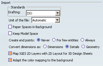
- Drafting
- The file you import is placed in a Drawing Representation. This
Drawing Representation style is defined in a pre-defined or a
customized standard such as ISO, JIS, ANSI, ASME. The drafting list lets you select this standard.
Note:
- The content of this list depends on which standards have been created and/or customized by your administrator.
- V6 determines systematically and automatically the most suitable
format (A0 ISO, A1 ISO, etc.) for each sheet (layout) i.e. V6
chooses the smallest format in which the drawing can be totally
included.
- If the standard is ISO, V6 chooses the format among A0, A1, A2, etc.
- If the standard is ANSI, V6 chooses the format among A, B, C, etc.
- If no standard format fits the sheet, the format is set to the largest one i.e. A0 ISO and made invisible with a message "No standard format can be applied to this sheet" in the report file.
- In export/import loops, the automatic determination of the standard may lead to format changes.
- If you are not satisfied with this automatic result, use the Page Setup command to modify the format.
Information on what has been determined automatically is written in the report file.
For more details about Drafting standards, please refer to Administration Tasks in the Interactive Drafting User's Guide.
 By default,
Drafting is set to ISO.
By default,
Drafting is set to ISO.
- Unit of the file
-
When this option is set to Automatic, the unit of import is determined automatically (either millimeter or inch) for the best possible resulting drawing.
However, in some cases the resulting drawing is not satisfactory and requires another unit. Select this unit in the list. Then restart the import.
By default,
Unit of the file is set to Automatic.
- Paper Spaces in Background
-
The Interactive Drafting workbench provides a simple method to manipulate a sheet. A sheet contains:
- a main view: a view which supports the geometry directly created in the sheet,
- a background view: a view dedicated to frames and title blocks,
- interactive or generated views.
Select this option to put the paper spaces in the background view. The viewports are created in the working view.
By default,
Paper Spaces in Background is not selected.
- Keep Model Space
-
Select this option to keep the entire model space in its own sheet.
If the option is not selected:
- When the model space is referenced at least partially by one or several viewports, it is not created in its own sheet.
- When the model space is referenced by no viewport (or if there is no viewport in the IGES 2D file), it is created in its own sheet (unless it is empty).
If the option is selected:
- The model space is created in its own sheet (unless it is empty).
During import, the management of views or drawings is automatic when the IGES 2D file is structured with Views and Drawings
By default,
Keep Model Space is not selected.
- Create end points
-
It is not easy to modify and stretch geometry of imported elements the way you can do it in a V6 native elements. A solution is to create end points when needed, but to the detriment of performances. Create end points offers you three options to fit your needs:
- Never: ensures the best performances.
- For few entities: creates end points only for hatch boundaries and mixed polylines. This is an intermediate choice between performances and edition capabilities.
- Always: creates end points for arcs, ellipses, lines, mlines, leaders and not standard polylines and splines. Use this option only when edition capabilities are required.
 By default,
Create end points is set to Never.
By default,
Create end points is set to Never.
- Convert dimensions as
-
Select the required option:
- Dimensions: linear, angular and circular dimensions are preserved, others (ordinate types) are transformed into details. This option keeps the semantic of the dimension. This means the position, the layout and the text are preserved. The position, color, thickness can be edited. The text of the dimension is a text that has an associative link with the dimension. This dimension has a "fake value" that is blanked. To display the true dimension value, delete the associated text and enter the data in the properties of the dimension.
- Geometry: geometry is exploded into multiple lines, arcs, texts. Select this option to keep the graphical aspect (this mode increase performance when loading a model).
- Details: turns dimensions into details. This is an halfway notion between the previous two, in which the geometry is preserved and the dimension is easy to handle (it can be all selected at once).
Important: - With the Dimensions option,
- Linear dimensions: rotated dimensions, i.e. linear dimensions with a fixed angle other than horizontal or vertical are turned into details,
- Radial dimensions: problems may occur while positioning arrows,
- Angular dimensions, problems may occur while positioning texts,
- Following attributes are not yet supported :
- suppression of one of the dimension lines (for half dimensioning),
- offset extension or suppression of extension lines,
- arrowhead choice (the V6 default arrowhead is used).
- With the Geometry and Details options, the arrowheads of form 1 (wedge) and 2 (triangle) are created as filled triangles.
By default,
Convert dimensions as is set to Details.
- Map IGES 2D Layers with 2D Layout for 3D Design Sheets
- This functionality is available only for 2D Layout for 3D Design workbench, using Import From File... command. When selected, it maps geometries and annotations with 2D Layout for 3D Design sheets, from the number of the layer the geometries and annotations belong to.
Note:
- Clipping views are not taken into account .
- An invisible layer in IGES 2D drawing is imported as a Layout sheet with its visualization status set to Hide in 3D.
Example:
- Entities in layer1 are in blue,
- Entities in layer2 are in red,
- Entities in layer3 are in green.
In this example, the IGES 2D Layout is imported in 2D Layout for 3D Design with 4 Layout sheets. The views of the first layout sheet have a display of the corresponding view on the different layout sheets.
- The name of the other layout sheets are: "initialSheetName" + "." + "layerIdInIG2File"
- Each IGES 2D sheet is converted into a Layout sheet containing as many views as there are viewports in the original sheet. Those views are created with entities belonging to layer none ("0" ). If the layer none contains no entity, the view is created empty.
- For each layer used in the original layout, an additional Layout sheet is created, containing the same views. IGES 2D geometries and annotations assigned to this layer are converted into V6 elements in those views.
- For each view, a display filter is created. This same filter is applied to each view of all the Layout sheets (corresponding to all layers, including the layer none).
- With a filter on the first Layout sheet, visualization is equivalent to the original IGES 2D
file.
- For a view, the name of this filter is: "MySheet.Name_of_View".
- The background visualization of all views in sheet "Mysheet" is set to Standard. The background visualization of all the views in other sheets corresponding to other layers is set to Low-intensified.
- If the data are imported with the option Keep Model Space, the Model Space is imported like another independent layout with one Main View. A filter Model is defined and give a display on each Main View of the different layouts. All entities in Model.1 are in layer1, All entities in Model.2 are in layer2, …
- Entities in paper space have a layer number. They are created in the corresponding layout.
- Layers on Details are not concerned by this dispatch of sheet.
By default,
Map IGES 2D Layers with 2D Layout for 3D Design Sheets is selected. - Adapt the color mapping to the background
- Select this option to change the Black and White colours entities, either to black or to white depending on the background colour.
By default,
Adapt the color mapping to the background is selected.
![]()
Export
- Exported sheets
-
Select the required option to export either all sheets or only the current sheet of a multi-sheet drawing:
- The option All exports the data to several files. The name of each file is made of the name entered in the Save as dialog box and the name of the sheet (Drawing1_sheet_1.ig2, Drawing_sheet_2.ig2, ...).
- The option Only current exports the data to a file with the name entered in the Save as dialog box.
By default,
Exported sheets is set to All.
- Export mode
-
This option offers now the choice between three export modes:
- Graphic: This mode is quick and reliable. It is useful if you want to export a drawing and print it without modifying it. It is the default mode.
- Structured: The exported file can be modified. For
example, in the case of a dimension exported in
Structured mode, all the graphic entities representing
the dimension are exported to an sub-figure. The more complex
drafting elements are exported the same way whereas the basic
geometric elements (lines, arcs, etc) are exported as isolated
elements.
Note: Dimensions are exported as subfigures and are editable as such.
- Semantic: This mode is similar to the
Structured mode, with the advantage that linear
dimensions are exported as true dimensions (with a default
dimension style) and editable as such.. "Default dimension style" entails that most
graphic attributes (such as color, display format of the dimension
value, type of arrow, space...) of the dimensions are lost.
- The texts of those dimensions (linear only) are exported with the IGES 2D corresponding font.
- Circular, angular and curvilinear dimensions are still exported as subfigures.
- Chamfer dimensions are exported as subfigures.
- Dimensions that cannot be exported semantically are exported as subfigures.
- Linear dimensions with:
- underlined text,
- text with frame,
- numerical values and decimal values given as fractions,
- funnels,
- half-dimensions,
- with an arrow pointing to the dimension line
- are exported as subfigures.
Note:
- for all modes:
- If the sheet to export contains no geometry, or only non supported entities, no IG2 file is generated.
- The visual clipping of views is not supported.
- Associative dimensions are not supported.
- for Semantic and Structured modes:
- Hidden objects: The V6 elements placed in the No Show are not exported. The visible elements are exported.
- Layers are automatically exported. The number of the IGES 2D layer is the number of the V6 layer.
- To avoid missing geometries at export, we recommend that you activate either the filter All Visible or the filter None.
-
Texts:
- All texts are exported as texts (even dimension texts in the case of dimensions exported as subfigures and annotations),
- All texts are exported and mapped automatically with the IGES 2D corresponding font,
- Kanji characters are exported with the IGES 2D 2001 font.
- The line thickness is automatically mapped, based on V6 current thickness.
For more information, see the V6 Data Exported to IGES 2D chapter.
By default,
Export mode is set to Graphic.