Linetype | ||
| ||
Linetype
The available linetypes are displayed in a list, the first eight types being grayed out as they correspond to the default linetypes (displayed in the Graphic Properties toolbar) and cannot be modified.
Important:
|
-
Double-click the linetype to be modified.
In the Linetype editor, you can define either mono-dimensional linetype, or a bi-dimensional linetype.
-
To define a mono-dimensional linetype, click Define a new mono-dimensional linetype. The Mono-dimensional linetype editor dialog box opens:
This dialog box lets you define the linetype to be used for visualization and print purposes.
-
In the Visualization definition box, click the desired squares to define the linetype pattern: a white square corresponds to a drawing, a black square corresponds to a blank. You can select up to 16 squares.
The Preview is updated accordingly as shown below:
-
Use the Factor arrows to stretch the pattern by increasing the value:
-
In the Print definition box, enter the length in millimeters for each pattern segment (do not forget to leave a blank space after each character you type).
A positive value indicates a drawing and a negative value indicates a move without drawing.
The capture below illustrates the print definition of the pattern defined in step 5:
-
Click OK to validate and close the dialog box.
The new linetype replaces the selected line in the Linetype editor list. If you do not wish to go on defining linetypes, click OK once again to close the Options dialog box.
-
To define a bi-dimensional linetype, double-click a line from the Bi-dimensional linetype list in the Linetype editor window.
-
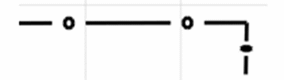
In the Bi-dimensional linetype editor window, move the cursor then click to create a segment and repeat these steps as necessary to define the desired pattern.
You can create segment breaks by double-clicking a point then moving the cursor to draw a new segment:
-
Use the following icons to:
-
 delete the whole pattern
 -
 delete the last segment
 -
 reframe the bi-dimensional line editor.
-
-
Click OK to validate and close the dialog box.
The linetype is displayed instead of the selected line at the end of the Linetype editor.
Click OK once again to close the Linetype editor and display the new linetype instead of the selected line at the end of the Linetype list.
| Important:
When the curve length is smaller than the length of the linetype pattern, a
compression factor has to be applied to the entire curve. Therefore, the
curve might look squeezed.
When a 2D linetype pattern is applied,
the number of patterns to be drawn is calculated as follows:
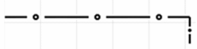
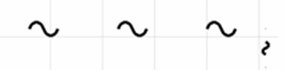
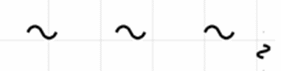
number of patterns = total curve length/pattern width This division is rounded off to the nearest integer value, which means that the drawn patterns are compressed or expanded so that they fit into the entire curve length. This is illustrated by the examples below:
You can see that at least one character is drawn, whatever the curve length. This means that patterns are compressed if the curve length is lower than the pattern width. |
![]()
Linetype Option
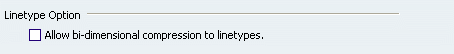
- Allow bi-dimensional compression to linetypes
If this option is selected, the compression factor is applied to both horizontal and vertical direction to keep the shape intact. Therefore, if a linetype contains curves or splines, they will not be deformed.
Example with circles
Linetype 18 - Thickness 2 Linetype 18 - Thickness 8 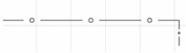
Example with splines
Linetype 18 - Thickness 2 Linetype 18 - Thickness 8 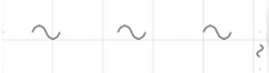
Inversely, if this option is cleared, the compression factor is applied to the linetype in a single direction. Therefore, if the linetype contains:
- curves (e.g. a circle), then they will be deformed into ellipses.
- splines, then they will be deformed.
Example with circles
Linetype 18 - Thickness 2 Linetype 18 - Thickness 8 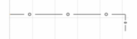
Example with splines
Linetype 18 - Thickness 2 Linetype 18 - Thickness 8 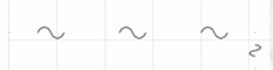
There is no need to restart V6 to take into account the activation or deactivation of the option.
 By default, this option is cleared.