Graphics | ||
| ||
Nodes

- Symbol
- This option lets you select the symbol you want to assign to the nodes of elements.
- Color
- This option lets you select the color of the chosen symbol to represent nodes of elements.
![]()
Elements

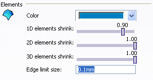
- Color
-
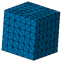
This option lets you choose the element color for meshes created with partner solutions.
Meshes that are created in the Finite Element Modeling workbench inherit the color from their supports (geometry or mesh). To modify the color of meshes created in the Finite Element Modeling workbench, use the Mesh Visualization Tools command in the Visualization Tools toolbar, or the Mesh Color contextual menu.
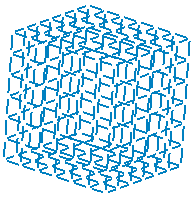
- 1D element shrink
-
This option lets you define the coefficient of shrink
visualization for 1D elements. You can modify the shrink
coefficient from 1.00 (default value) to
0.50 (minimum value).


 By default,
the shrink value for 1D elements is equal to 1.00 (i.e.
no shrink visualization).
 - 2D element shrink
- This option lets you define the coefficient of shrink
visualization for 2D elements. You can modify the shrink
coefficient from 1.00 (default value) to
0.50 (minimum value).


 By default,
the shrink value for 2D elements is equal to 1.00 (i.e.
no shrink visualization).
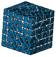
 - 3D element shrink
- This option lets you define the coefficient of shrink
visualization for 3D elements. You can modify the shrink
coefficient from 1.00 (default value) to
0.50 (minimum value).


 By default,
the shrink value for 3D elements is equal to 1.00 (i.e.
no shrink visualization).
 - Edge limit size
- This option lets you define the mesh tolerance under
which two circles is added to the visualization of
BAR elements.
 By default,
this value is equal to 0.01mm.