Display | ||
| ||
Fastener Technological Parameters
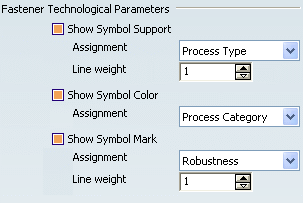
- Show Symbol Support
-
Select the Show Symbol Support option to visualize the
fastener technological symbol support.
 By default,
this option is selected.
From the Assignment combo list, select:
- Process Type: the symbol support is displayed
according to the symbol code assigned to the reference fastener
type.
By default, if no symbol is assigned to reference fastener type,
the symbol code value is
 (101)
(101) By default,
this option is set to Process Type.
- Unspecified: the default symbol support
 is displayed. It can be modified through
the Properties contextual command.
- Zone Count: the symbol is displayed according to symbol
code assigned to the number of joined zones set in the Fst_Standard
file.
By default, if no symbol is assigned to the thickness count in
standard, or if there is no imported standard, the symbol is:
 for 1 thicknesses (1)
 for 2 thicknesses (2T)
 for 3 thicknesses (3T)
 for 4 thicknesses (4T)
 for more than 4 thicknesses
 By default,
the Symbol Support is assigned to Process
Type.
From the Line weight drop-down list, select a value from 1 to 3.
Zone Count selected, Line weight = 1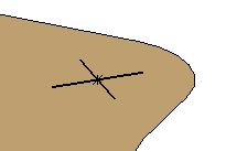 Zone Count selected, Line weight = 3
 By default,
the value is set to 1.
Once the symbol is associated with a specification, it can no longer be modified when editing the fastener properties, except for the Unspecified type.
- Process Type: the symbol support is displayed
according to the symbol code assigned to the reference fastener
type.
By default, if no symbol is assigned to reference fastener type,
the symbol code value is
- Show Symbol Color
-
Select the Show Symbol Color option to visualize the
fastener color.
 By default,
this option is selected.
From the Assignment combo list, select:
- Process Category: the color is displayed according
to the color code assigned to the Fastener Process Category in the
standard file.
By default, if no color is assigned to the Process Category, the
default color is:
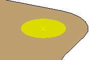
- Yellow for Welding
- Cyan for Adhesive
- Magenta for Sealant
- Green for BiW Mechanical
- White for Unspecified
Here is an example for Welding:
- Unspecified: the color is white whatever the process
category:

 By default,
the Symbol Color is assigned to Process
Category.
Once the color is associated with a specification, it can not longer be modified when editing the fastener's properties, except for the Unspecified type.
From the Line weight drop-down list, select a value from 1 to 3.
 By default,
the value is set to 1.
 - Process Category: the color is displayed according
to the color code assigned to the Fastener Process Category in the
standard file.
By default, if no color is assigned to the Process Category, the
default color is:
- Show Symbol Mark
- Select the Show Symbol Mark option to visualize the mark
(displayed as a half-diamond).
 By default,
this option is selected.
From the Assignment combo list, select the fastener classification parameter:
- Robustness
- Regulation
- Finish
Note that:
- 1 is for assigning a mark
- 0 is for assigning no mark
This mark is customized through the Fst_Standard file in order to be representative of the a specific fastener classification value.
Here is an instance with "Robustness=Safety":

Therefore, if you assign the 1 mark code for the parameter and value (Robustness=Safety), you will get this Mark:
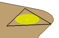
In this case all the fasteners with the same parameter and value will get the mark symbol.
From the Line weight drop-down list, select a value from 1 to 3.
 By default,
the value is set to 1.
![]()
Fastener Shape Parameters

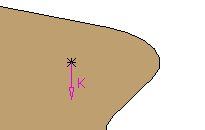
- K Axis Display Only
Click K Axis Display Only to specify the visualization type of the fastener axis (K axis only or I, J, K axis).
 By default,
this option is selected.
- if selected, only the K axis is visualized on the fastener
location:
- If not selected, a trihedron showing the fastener axis system (I,
J, K) is visualized on the fastener location:
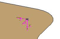
Here the fastener axis orientation is shown through the graphic properties of this fastener.
For detailed information on the display (show/no show) of the fastener parameters, refer to Editing the Fasteners Properties.
- if selected, only the K axis is visualized on the fastener
location: