Adjusting Design Layout | |||
| |||
Move in Same Direction
You can adjust the layout of a network by moving a part in one direction.
Click Modify
 in the Compass Toolbar.
Select Manipulate
 > Adjust
  >
Adjust Same Direction
>
Adjust Same Direction  in the balloon.
The robot places on the part.
Drag along the vertical direction and drop it at the required distance.
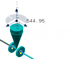
Click Commit
 .
.The selected part is moved by the selected distance. The affected layout is highlighted in red color.
Click Update all
 .
.
The layout is updated.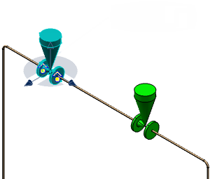
Note: If the distance between the two parts becomes lesser than half of the minimum straight distance, then the pipe between the parts is removed and parts are connected together.
![]()
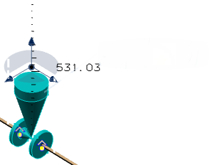
Orient with New Corner
You can adjust the layout by orienting new corners.
Click Modify
in the Compass Toolbar.Click Manipulate
> Adjust >
Adjust by Making New Corner at New Location  in the balloon.
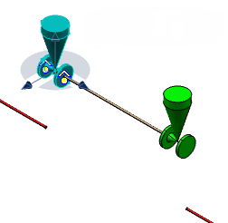
The robot places on the part.
Drag along the X-direction and drop it at the required distance.
Click Commit
.The selected part is moved by the selected distance. The affected layout is highlighted in red color.
Click Update all
.
New corners are formed. The layout is updated.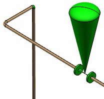
![]()
Modify with New Corner
You can adjust the layout by creating new corners at the minimum straight distance.
Click Modify
in the Compass Toolbar.Click Manipulate
> Adjust >
Adjust by Making New Corner at Minimum Straight Distance  in the balloon.
The robot places on the part.
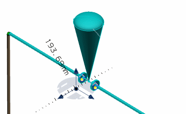
Drag along the X-direction and drop it at the required distance.
Click Commit
.The selected part is moved by the selected distance. The affected layout is highlighted in red color.
Click Update all
.
New corners are formed. The layout is updated.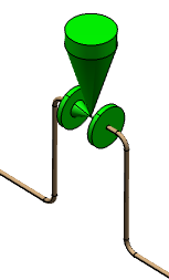
Note:
- The Adjust by Making New Corner at Minimum Straight Distance and Adjust by Making New Corner at New Location options are available for piping parts only.
- You cannot select an equipment, a flexible pipe or a support to move when adjusting the network layout.