About Logical to Physical | ||
| ||
About Logical
The logical data created in the VPM Functional Logical Editor workbench is used in the Fluid Systems Design to create the piping layout and predefined parts.
In the VPM Functional Logical Editor workbench, the logical structure and physical structure is created.
The logical structure is created under the Logical node in the RFLP tree structure. For more information about creating logical system, refer to Fluid Systems Logical Editor User's Guide.
The logical structure consists of :
- Equipment
- Piping Parts
- Pipes
- Piping Ports
The part number of the physical component from the catalog is defined in the Predefined Part Number box of the logical component.
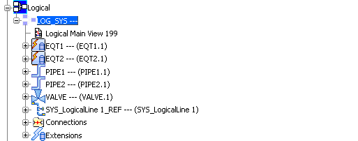
Example of a fluid logical system:
Specification tree organization
 |
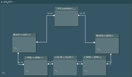
2D layout
 |
To create the 3D representation of the logical components, see VPM Functional Logical Editor User's Guide: Functional and Logical Definition: Creating 3D Representation for Logical Components.
The pathways are created in the Logical 3D Architecture workbench. For more information about creating pathways, see Logical 3D Architecture User's Guide: Working with Pathways: Creating Pathways.
![]()
About Physical
The physical structure is created under the Physical node in the RFLP tree structure.
The physical structure consists of:
- Equipment
- Rigid Pipes
- Flexible Pipes
- Piping Parts
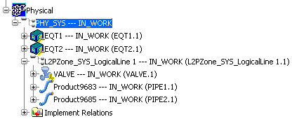
Example of a physical structure:
Specification tree organization
 |
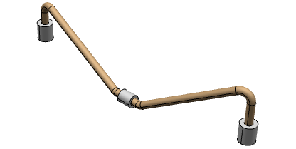
3D design
 |
For synchronizing the logical information with the physical one, it is essential to create implement links. These implement links are used to connect elements of different abstraction levels. For more information, refer to VPM Functional Logical Editor User's Guide: Implement: Creating Implement Relations.
The physical equipment can be placed in the 3D representation of the logical component in the Fluid Systems Detail Design workbench using the Place Part command in the West toolbar. You can move the part in the 3D geometry area using the Modify command in the West toolbar.
If the predefined numbers are correctly defined in the logical equipment, the corresponding physical elements can be synchronized using the Logical to Physical command. The implement relation is automatically created between the physical and logical equipment when the physical equipment is synchronized.