Compatibility Rules Definition Table | ||
| ||
Overview
This section provides a brief overview of the Compatibility Rules.
The compatibility rules ensure that when you are placing parts and creating routes, the parts you choose are compatible with one another and with the route.
The compatibility rules will:
- Filter part selection.
- Flip parts correctly.
In Project Resource Management, this definition table should be assigned to:
The Compatibility Rules Definition Table item in the resource table of Piping/Tubing Design Resources.
Click , and in the Options dialog box select and select the Perform compatibility checking check box.
Note: This setting is considered only for the attribute Nominal Size, while placing a part on a segment or interior node.
![]()
Rule Customization
This section describes the customization options of the Compatibility Rules.
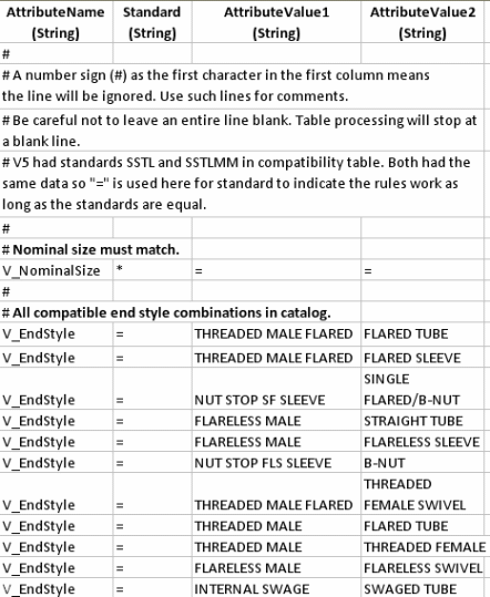
A typical
Compatibility Rules Definition Table is shown below (it has
been modified slightly to make it fit in
this space). 
Compatibility is established by entering in the table the attribute values that are considered compatible. The table shows tubing parts, however the rule behaves as explained for all types of parts.
AttributeName: The attribute name. Note that this must always be preceded by V_.
Standard: The standard to which this will apply. Only parts with the listed standard will be filtered and made available for selection.
AttributeValue1: The value that is to be compatible with AttributeValue2, which is on the second part.
AttributeValue2: The value that is to be compatible with AttributeValue1, which is on the first part.
Two special symbols can be used in the table.
Equal sign (=): When typed in the Standards column, it means the standard for both parts must be the same. When typed in the AttributeValue1 and AttributeValue2 columns, it means that the values for both parts must be the same.
Asterisk (*): When typed in a column the meaning is similar to that of a wild card. In the Standards column it means that the listed attribute values are compatible even if they have different standards. When typed in an AttributeValue column it means that any value is compatible.
Examples
Some
examples are:
Line 1: IRON Rating attributes with the same values are compatible.
Line 2: Same as Line 1, but for ASTL – all ASTL Rating attributes that have the same value are compatible.
Line 3: For the standard ASTL, a Rating value of 150 is compatible with any other ASTL Rating.
Line 4: Nominal Size attributes are compatible if they have the same standard and the same value.
Line 5: All equal Shape are compatible. However, the asterisk in the standard column says that shapes are compatible even for different standards. Thus a port with a Shape value of ROUND and standard ASTL is compatible with a port that also has Shape ROUND but standard IRON. On the other hand, an ASTL port and an IRON port both with Nominal Size 2in are not compatible because their standards are different.
You can
add a column for a second standard, to
specify that values for the two defined
standards are compatible.
In the table above, ASTL Rating 300 matches IRON Rating 250, and ASTL Rating 150 matches IRON Rating 125. In the absence of any other lines, all other Rating values are incompatible. In tables with a second standard column, lines specifying only one standard can leave the second standard blank.