Automatic Part Rules Definition Table | ||
| ||
Overview
This section provides a brief overview of the Automatic Part Rules.
The automatic part rules free you from routine chores that have to be repeated during the course of part placement.
By using the automatic part rules administrators can define parts that will be placed automatically when two main parts are detected next to each other. A typical example is the automatic insertion of a gasket between two parts which each have a raised face endstyle.
In Project Resource Management, this definition table should be assigned to:
The Automatic Part Rules Definition Table item in the resource table of Piping/Tubing Design Resources.
![]()
Rule Customization
This section describes the customization options of the Automatic Part Rules.
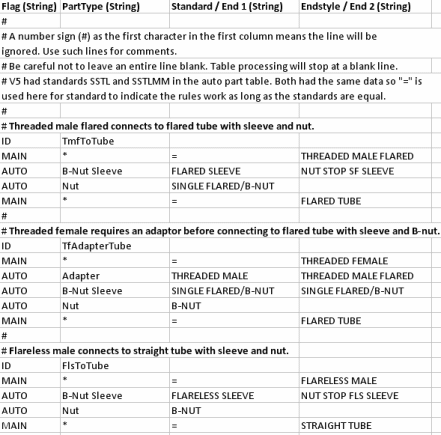
A typical Automatic Part Rules Definition Table is shown below.
The automatic part rules table can contain one or many rules.
A rule defines two main parts, and one or more automatic parts that will go between them.
Flag: Identifies the two main parts and one or more automatic parts. The first entry - ID - in each rule set defines a title to help users. This is the ID shown to the user in case there are multiple rule sets found in the table for the same endstyle combinations.
PartType: The part type of the main and automatic parts.
Standard/End 1: For main parts type the standard. For automatic parts type Endstyle 1. Endstyle 1 will connect to the first main part defined in the rule set.
Endstyle/End 2: For main parts type the endstyle. For automatic parts type Endstyle 2. Endstyle 2 will connect to the second main part, or the next automatic part if more than one is defined in the rule set.
- If no endstyles are entered for an automatic part then the flip direction will be arbitrary. If one endstyle is entered then the flip direction will be taken into account.
- If "none" is entered as the value for one of the endstyles, then it will mean the part only has one endstyle. This may be useful for filtering nuts.
Two special symbols can be used in the table.
Equal sign (=): When typed in the =Standards/End 1 column, it means both main parts must have the same standard.
Asterisk (*): When typed in a column the meaning is similar to that of a wild card, meaning "all".
Example
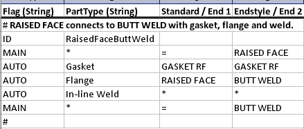
The following rule set is
an extract from the Automatic Part Rules Definition Table.
The meaning is explained below.

The comment notes that when a part with a raised face endstyle is placed next to a part with a butt weld endstyle, then the following automatic parts will be placed between them when the automatic parts command is executed: gasket, flange, in-line weld (in that order).
The rule set ID is RaisedFaceButtWeld.
The entries in the rule set are:
- Main parts can have any part type, and should have the same standard. The first main part has the raised face endstyle, and the second main part has the butt weld endstyle.
Automatic parts are:
- Gasket part type, with gasket RF as Endstyle 1 and Endstyle 2.
- Flange part type, with raised face as Endstyle 1 and butt weld as Endstyle 2.
- In-line weld part type, with any end style.